Plasma display apparatus

Inactive Publication Date: 2007-05-31
LG ELECTRONICS INC
View PDF3 Cites 10 Cited by
  • Summary
  • Abstract
  • Description
  • Claims
  • Application Information

AI Technical Summary

Benefits of technology

[0014] The present invention is to provide a plasma display apparatus for sharing one sustain electrode between two neighbor cells, thereby reducing a panel capacitance and

Problems solved by technology

This increases a capacitance between the neighbor cells, serving as a disadvantage in wall charge formation and power consumption in view of driving the panel.
Accordingly, the conventional YZZY type electrode structure has a drawback that luminance value is not uniform on the whole since the

Method used


Image

  • Plasma display apparatus
  • Plasma display apparatus
  • Plasma display apparatus

Examples


Embodiment Construction

[0025] Preferred embodiments of the present invention will be described in a more detailed manner with reference to the drawings.

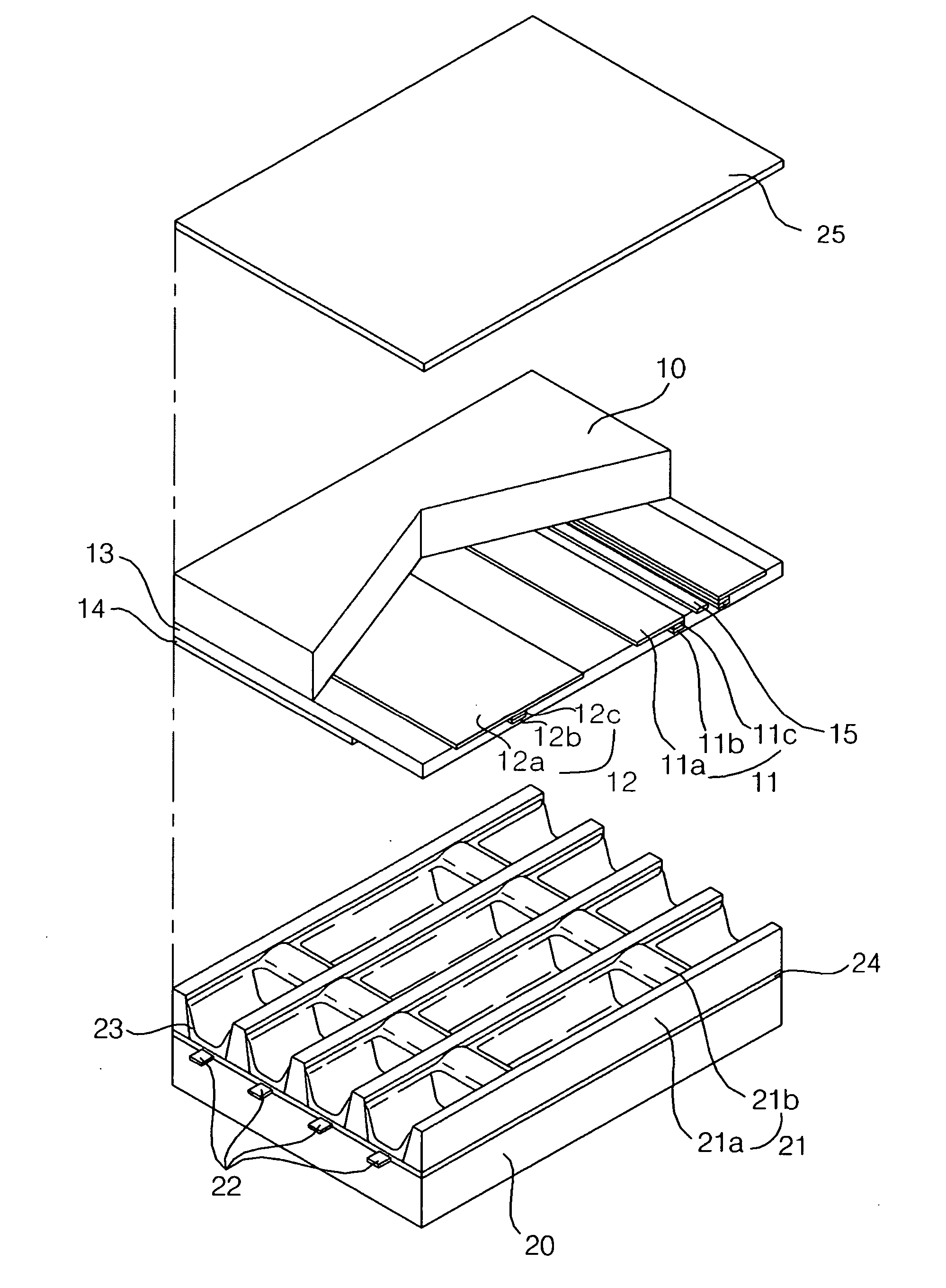
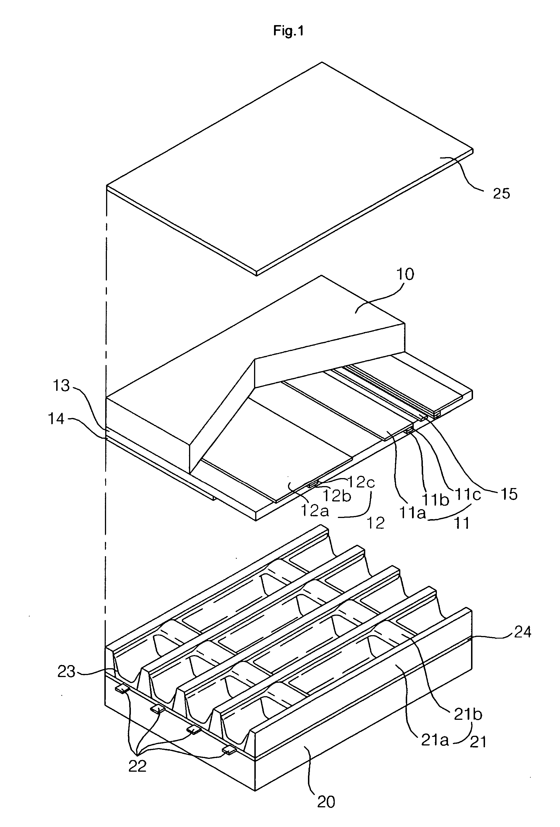
[0026]FIG. 1 is a perspective view illustrating a structure of a plasma display panel according to an exemplary embodiment of the present invention.

[0027] As shown in FIG. 1, the plasma display panel includes a scan electrode 11 and a sustain electrode 12 that constitute a sustain electrode pair formed on a front substrate 10; and an address electrode 22 formed on a rear substrate 20.

[0028] The sustain electrode pair 11 and 12 includes transparent electrodes 11a and 12a, and bus electrodes 11b and 12b. The transparent electrodes 11a and 12a are formed of Indium-Tin-Oxide (ITO). The bus electrodes 11b and 12b can be formed of metal such as silver (Ag) and chrome (Cr). Alternately, the bus electrodes 11b and 12b can be of laminate type based on chrome / copper / chrome (Cr / Cu / Cr) or chrome / aluminum / chrome (Cr / Al / Cr). The bus electrodes 11b and 12b are formed ...


PUM


Abstract

Provided is a plasma display apparatus. The plasma display apparatus includes a scan electrode and a sustain electrode, a boundary barrier rib, and a filter. The scan and sustain electrodes are formed in parallel with each other on a front substrate. The boundary barrier rib is formed on a rear substrate facing the front substrate, and partitions a discharge cell into two up/down neighbor cells. The filter is positioned in front of a panel. The filter includes an external light shield sheet including a first base part and a first pattern part, and an ElectroMagnetic Interference (EMI) shield sheet. A thickness of the external light shield sheet is 1.01 to 2.25 times of a height of the first pattern part. The sustain electrode is commonly formed only one for the two up/down neighbor cells.

Description

[0001] This Nonprovisional application claims priority under 35 U.S.C. §119(a) on Patent Application No. 10-2005-0114893 filed in Korea on Nov. 29, 2005, the entire contents of which are hereby incorporated by reference. BACKGROUND OF THE INVENTION [0002] 1. Field of the Invention [0003] The present invention relates to a plasma display apparatus, and more particularly, to a plasma display apparatus for shielding external light, thereby improving contrast, and preventing cross-talk between two neighbor cells, thereby preventing erroneous discharge and reducing power consumption, and increasing an aperture ratio of a cell, thereby improving luminance. [0004] 2. Description of the Background Art [0005] Plasma Display Panel (PDP) refers to a device for applying a predetermined voltage to electrodes installed in a discharge space, inducing discharge, and exciting phosphors by plasma generated by gas discharge, thereby displaying an image including a character or a graphic. The plasma di...

Claims


Application Information

Patent Timeline
IPC IPC(8): H01J17/49H01J11/12H01J11/24H01J11/44
CPCH01J11/12H01J11/24H01J11/44H01J2211/444H01J2211/446
Inventor KIM
Owner LG ELECTRONICS INC
Why Eureka
Try Eureka