Vapor phase growth apparatus and method of fabricating epitaxial wafer

a growth apparatus and vapor phase technology, applied in the direction of liquid displacement, separation processes, antibody medical ingredients, etc., can solve the problem of difficulty in obtaining the desired distribution of film thickness, and achieve the effect of reducing the degree of pattern deformation and maximizing the effect of controlling direction

Inactive Publication Date: 2007-05-31
SHIN-ETSU HANDOTAI CO LTD
View PDF0 Cites 18 Cited by
  • Summary
  • Abstract
  • Description
  • Claims
  • Application Information

AI Technical Summary

Benefits of technology

[0014] In the vapor phase growth apparatus of this invention, the guide component for the source gas is disposed on the top surface of the bank component. The source gas climbing up onto the top surface of the bank component is largely limited in the flow thereof in the width-wise direction by the guide component. Because the flow route in the width-wise direction of the source gas flowing over the substrate placed just downstream of the bank component can thus be controlled by partitioning the flow of the source gas directed towards the susceptor in the width-wise direction on the top surface of the bank component, it is made possible to obtain a silicon single crystal film having a more uniform distribution of the film thickness.
[0021] It is also allowable for the vapor phase growth apparatus of this invention to be provided with an evacuation system keeping the inner space of the reaction vessel under a reduced pressure lower than the atmospheric pressure. This configuration allows epitaxial growth under a reduced pressure condition contributive to reduction in the degree of pattern deformation, when it is desired to proceed the vapor phase growth on a substrate having patterns already formed thereon.

Problems solved by technology

Typical known problems in the vapor phase epitaxial growth of the silicon single crystal film on the silicon single crystal substrate include deformation of a pattern.
Epitaxial growth under a reduced pressure condition using the apparatus such as described in the aforementioned Japanese Laid-Open Patent Publication “Tokkaihei” No. 7-193015 may, however, sometimes encounters a difficulty in obtaining a desired distribution of film thickness.

Method used


Image

  • Vapor phase growth apparatus and method of fabricating epitaxial wafer
  • Vapor phase growth apparatus and method of fabricating epitaxial wafer
  • Vapor phase growth apparatus and method of fabricating epitaxial wafer

Examples


experimental cases

(Computer Simulation Experiments)

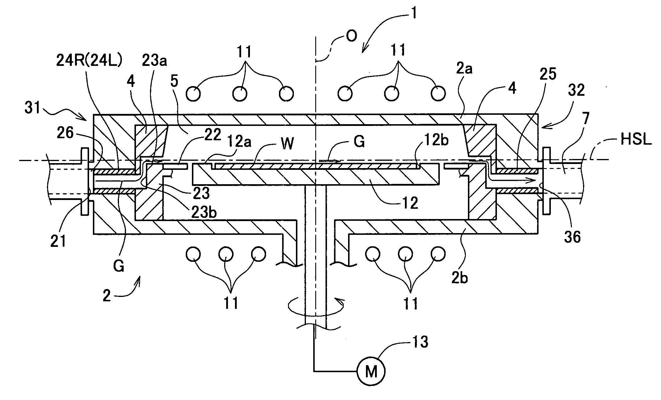
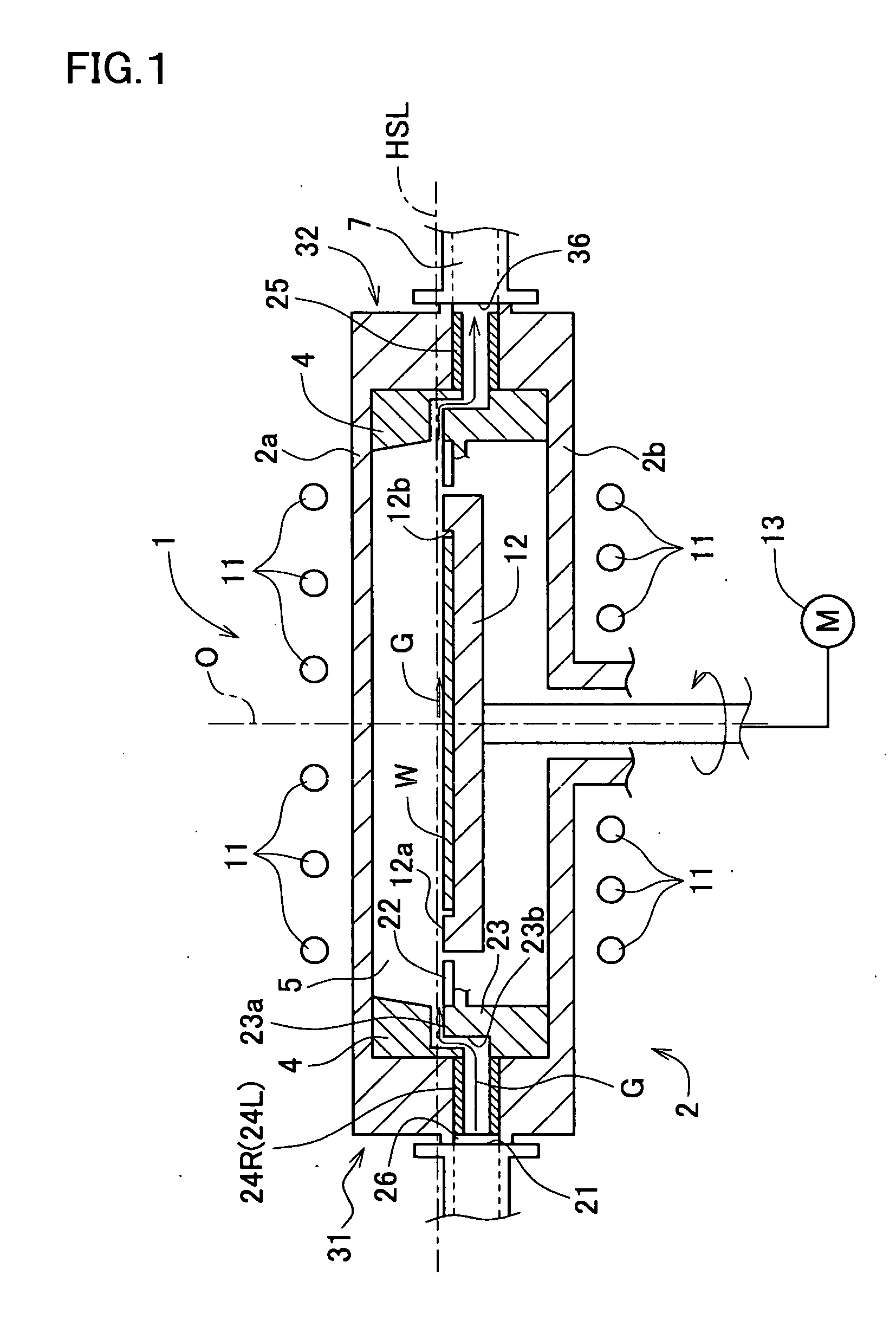
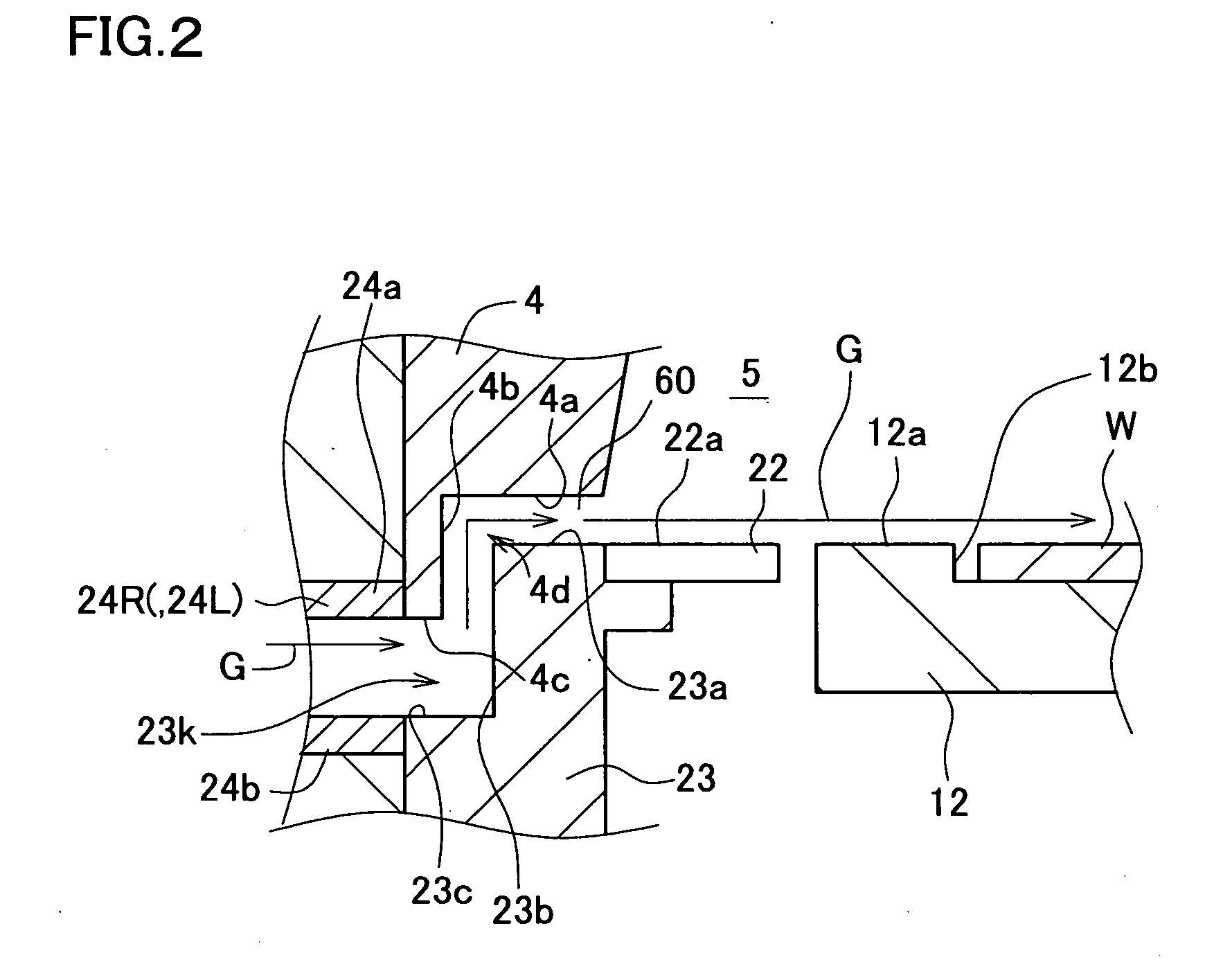
[0062] A flow route of the source gas in the vapor phase growth apparatus 1 as shown in FIGS. 1 to 4 was found by computer simulation. For the comparative purpose, also a flow route of the source gas in a conventional vapor phase growth apparatus having no guide plates 40R, 40L, 41R, 41L was found. A growth rate distribution of the silicon single crystal film when it is epitaxially grown on the silicon single crystal substrate W in the vapor phase growth apparatus shown in FIGS. 1 to 4 was estimated by computer simulation. For the comparative purpose, also a growth rate distribution of the silicon single crystal film when it is epitaxially grown on the silicon single crystal substrate in the conventional vapor phase growth apparatus having no guide plates 40R, 40L, 41R, 41L was estimated. Set conditions were as listed below.

Software: Fluent Ver 6.0 (product of Fluent Asia Pacific Co., Ltd.)

(Dimensions)

[0063] Diameter of reaction vessel=300 mm ...


PUM

PropertyMeasurementUnit
diameteraaaaaaaaaa
diameteraaaaaaaaaa
widthaaaaaaaaaa

Abstract

A vapor growth device which is constituted as a single-wafer type and has a gas introducing port through which a material gas is led into a reaction vessel. A dam member is disposed around a susceptor, and the material gas from the gas introducing port hits the outer peripheral surface of the dam ring and rides on an upper surface side, and then is allowed to flow along the main surface of a silicon single-crystal substrate placed on the susceptor. Guide plates for dividing the flow in the width direction of the material gas are disposed on the upper surface of the dam member. Accordingly, a vapor growth device capable of controlling the flow rate of material gas flowing on a silicon single-crystal substrate, and a production method for an epitaxial wafer using it are provided.

Description

BACKGROUND OF THE INVENTION [0001] 1. Field of the Invention [0002] This invention relates to a vapor phase growth apparatus allowing vapor phase growth of a silicon single crystal film on the main surface of a silicon single crystal substrate to proceed therein, and a method of fabricating an epitaxial wafer realized using the same. [0003] 2. Description of the Related Art [0004] Silicon epitaxial wafer having a silicon single crystal film (simply referred to as “film”, hereinafter) grown in vapor phase on the main surface of a silicon single crystal substrate (simply referred to as “substrate”, hereinafter) is widely used for electronic devices such as bipolar IC, MOS-IC and so forth. With advancement in micronization of the electronic devices, requirement for flatness of the main surface of the epitaxial wafer in which the devices are fabricated has been becoming more stringent. Causal factors affecting the flatness include flatness of the substrate and distribution of the film t...

Claims


Application Information

Patent Timeline
Patent Type & Authority Applications(United States)
IPC IPC(8): A61K39/02B01D5/00B01D12/00C23C16/24C23C16/44C23C16/455H01L21/205
CPCC23C16/45587C30B25/14C30B29/06C23C16/24
Inventor YAMADA, TORUYAGI, SHINICHIRO
Owner SHIN-ETSU HANDOTAI CO LTD
Why Eureka
Try Eureka