

Fuel injection system
- Summary
- Abstract
- Description
- Claims
- Application Information
AI Technical Summary
Benefits of technology
Problems solved by technology
Method used
Image

Examples
first embodiment
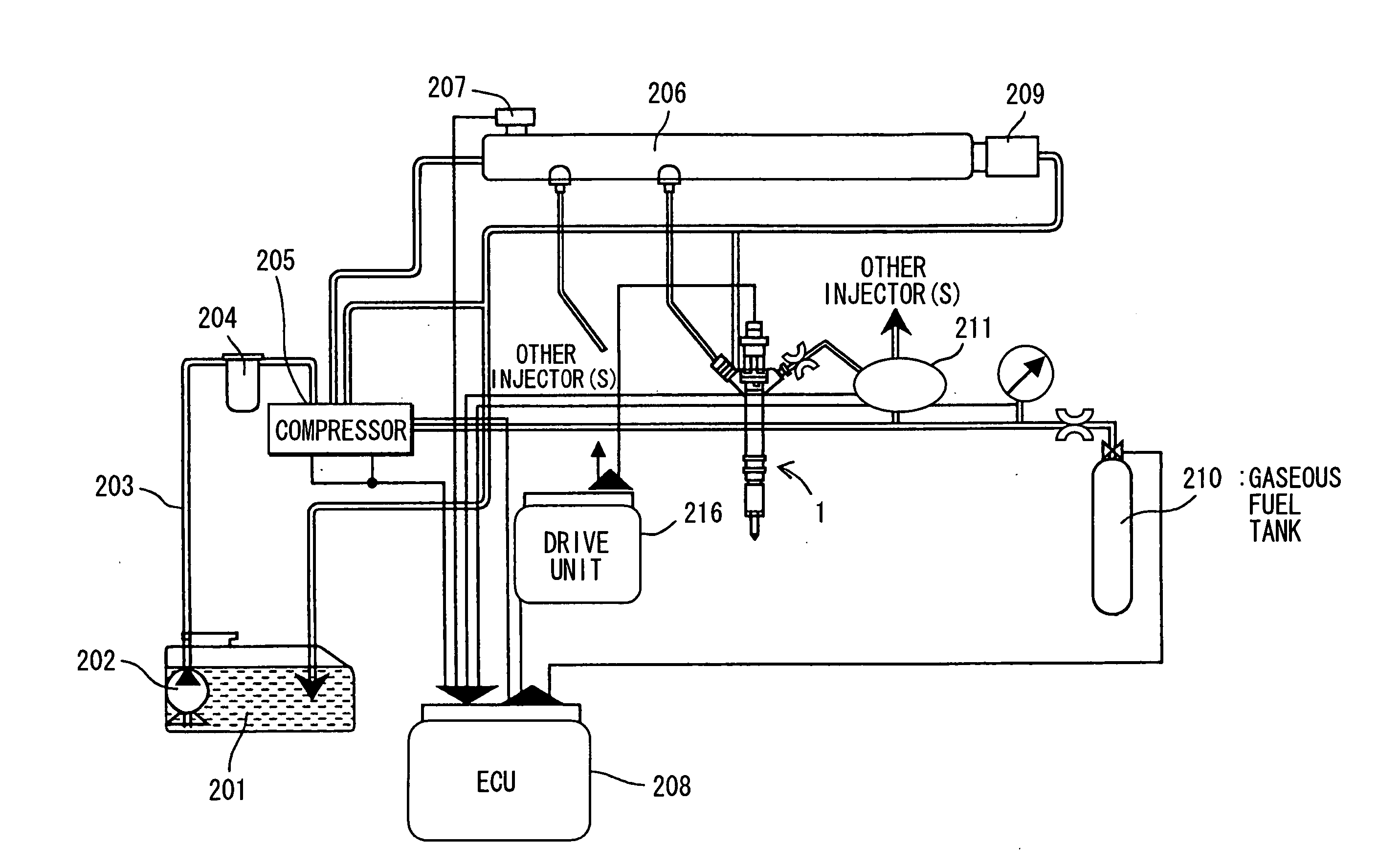
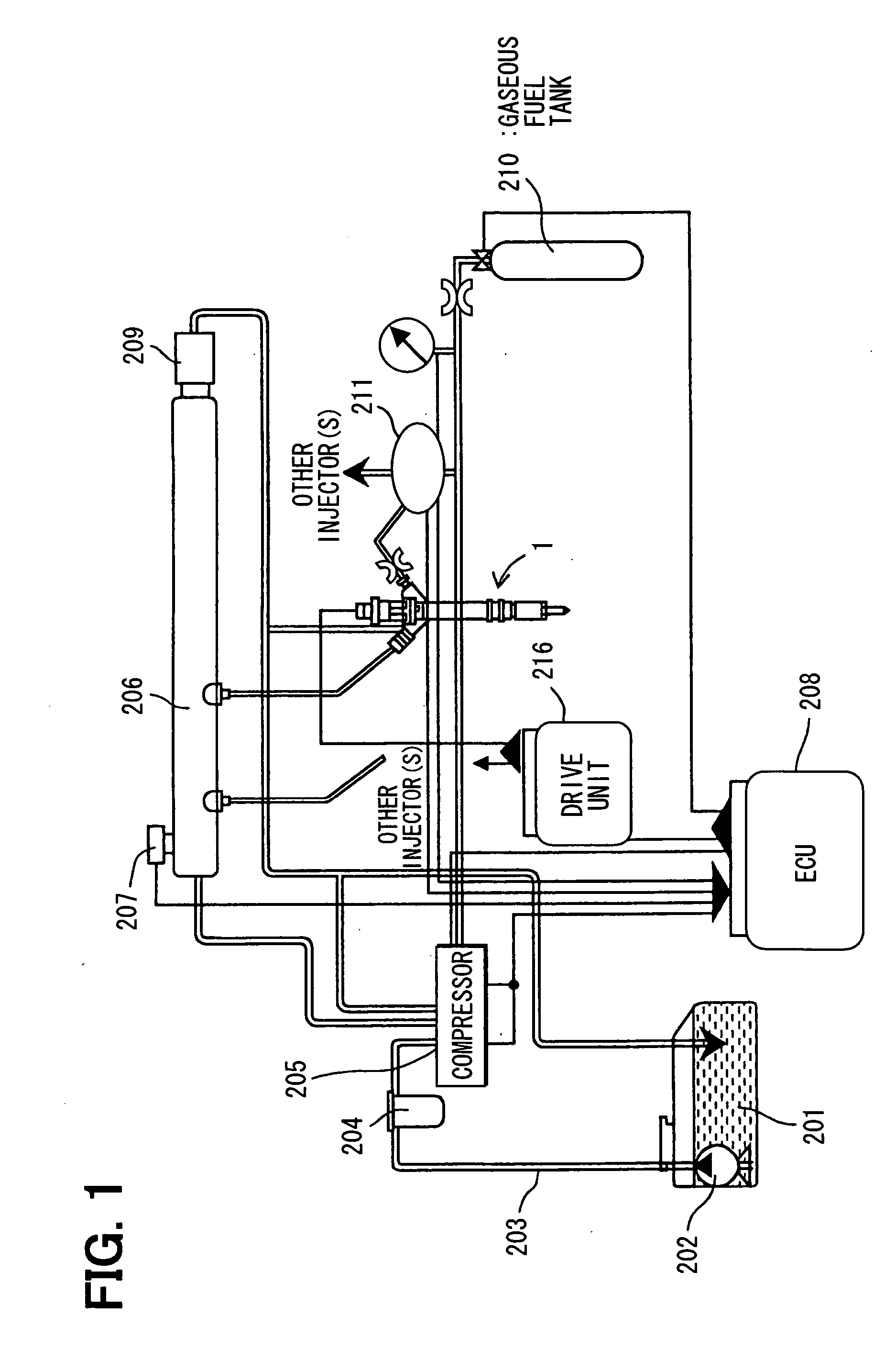
[0038] A fuel injection system is fabricated as an embodiment of the invention. FIG. 1 illustrates a configuration of the fuel injection system in this embodiment.
[0039] The fuel injection system in this embodiment pressure feeds liquid fuel such as light oil and gaseous fuel such as hydrogen to an injector 1 as one of multiple injectors, and injects them from the injector 1. Description will be given to the configuration of the fuel injection system in this embodiment, together with paths for fuels.
[0040] First, description will be given to the path through which liquid fuel such as light oil is pressure fed to the injector 1.
[0041] The light oil (liquid fuel) to be injected from the injector 1 is stored in a liquid fuel tank 201. The light oil is drawn from the liquid fuel tank 201 by a feed pump 202. The liquid fuel goes through a pipe 203. Fine dust, moisture, and foreign matter mixed in the liquid fuel are removed through a filter 204. Then, the light oil is pressurized to a...
second embodiment
[0081] This embodiment is a modification to the first embodiment. It is a system having a compressor 205, structure of which is simplified by disusing the pipe extending from the feed pump 202 to the first control chamber and the pipe extending from the first control chamber to the common rail. FIG. 10 shows the compressor 205 in this embodiment. The members of the compressor 205 in this embodiment, that are not specially referred to are those having the same function and structure as of the compressor in the first embodiment.
[0082] The liquid fuel pressure fed from the feed pump 202 pushes a third valve 410 open and goes into a second control chamber 402. At this time, the gaseous fuel pressure fed from the gaseous fuel tank 210 goes into a third control chamber 403 by way of a pressure control valve 406.
[0083] When the gaseous fuel pushes the plane A 412 of a pressure piston 405, the pressure piston 405 slides to the left. When the pressure piston 405 slides to the left, the vol...
third embodiment
[0085] This embodiment is a modification to the first embodiment and is a system having a compressor 205 illustrated in FIG. 11. The members of the compressor 205 in this embodiment, that are not specially referred to are those having the same function and structure as of the compressor in the first embodiment.
[0086] The compressor 205 is constructed of a first control chamber 501, second control chamber 502, third control chamber 503, fourth control chamber 504, pressure piston 505, pressure control valve 506, position sensor 507, first valve 508, second valve 509, third valve 510, and fourth valve 511.
[0087] The compressor 205 in this embodiment is different from the compressor in the first embodiment in that the destinations of pipes for gaseous fuel and liquid fuel are reverse. That is, the first valve 508 and the second valve 509 are connected to the third control chamber 503, and the third valve 510 and the fourth valve 511 are connected to the fourth control chamber 504.
[0...
PUM
 Abstract
Description
Claims
Application Information