Electrodeless gas discharge lamp

a technology of electric discharge lamp and gas discharge tube, which is applied in the direction of discharge tube/lamp details, magnetic discharge control, gas-filled discharge tube, etc., can solve the problem of large amount of electromagnetic interference, and achieve the effect of uniform field intensities and current densities, excellent coupling and excellent coupling

Inactive Publication Date: 2007-06-21
MINEBEA CO LTD
View PDF9 Cites 15 Cited by
  • Summary
  • Abstract
  • Description
  • Claims
  • Application Information

AI Technical Summary

Benefits of technology

[0010] According to the invention, the electrodeless gas discharge lamp is constructed in the same way as a conventional transformer. It uses a closed core made of a soft magnetic material, such as ferrite, the core being, for example, a UU-core or a UI-core. The closed core can also be described as ring-shaped, although its shape need not be rotationally symmetric but rather resemble a closed rectangular or polygonal ring. The core comprises at least one substantially straight leg, particularly two parallel straight legs, with either one or both legs carrying an exciter winding that forms the primary coil of the transformer and induces the gas discharge in the discharge vessel. The discharge vessel takes the form of a hollow cylindrical ring that encloses the wound leg at a short spacing. As a result of the oscillating magnetic flux in the core, closed field lines are produced in the discharge vessel along which free charge carriers are accelerated and excite atoms of the active medium through collision processes. The oscillating magnetic flux is generated by means of the high frequency alternating voltage at the primary winding or through the resulting current flow respectively. The choice of active medium is determined by the requirement placed on light efficiency and spectral distribution. The amount of gas pressure is determined on the basis of optimum light efficiency or on the basis of ignition criteria. Ignitability requires low gas pressure in the millibar range or lower. Due to the spatially confined arrangement between the plasma current generated in the discharge vessel and the inducing current in the exciter winding, external magnetic fields are largely annihilated, or expressed otherwise: due to the excellent coupling between the primary and secondary coil (plasma), interference radiation is extensively precluded. The geometry of the core, exciter winding and discharge vessel proposed in the present invention makes it possible to achieve uniform field intensities and current densities in the entire discharge region. This results in optimum conditions for light emission and for efficiency over the entire length of the lamp.

Problems solved by technology

All electrodeless gas discharge lamps of the prior art have the disadvantage that they generate an extensive amount of electromagnetic interference.

Method used


Image

  • Electrodeless gas discharge lamp
  • Electrodeless gas discharge lamp
  • Electrodeless gas discharge lamp

Examples


Embodiment Construction

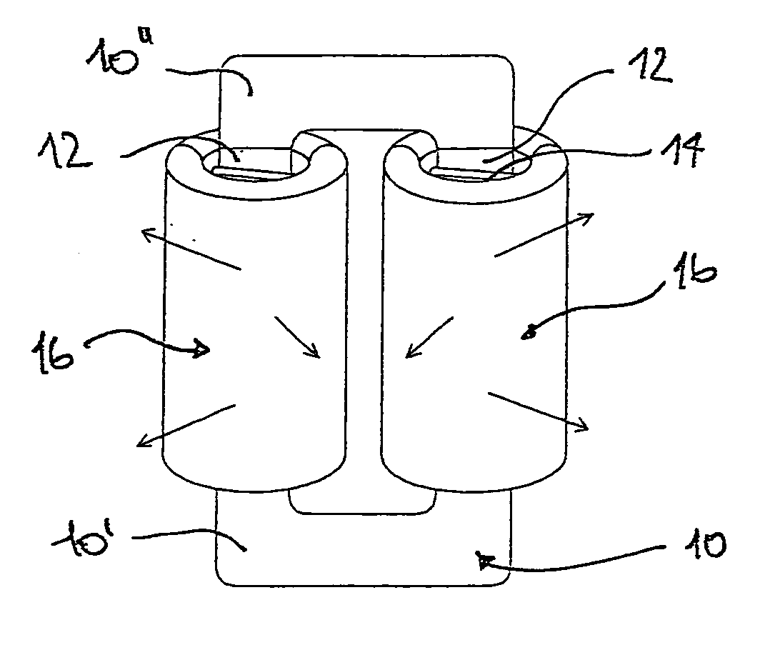
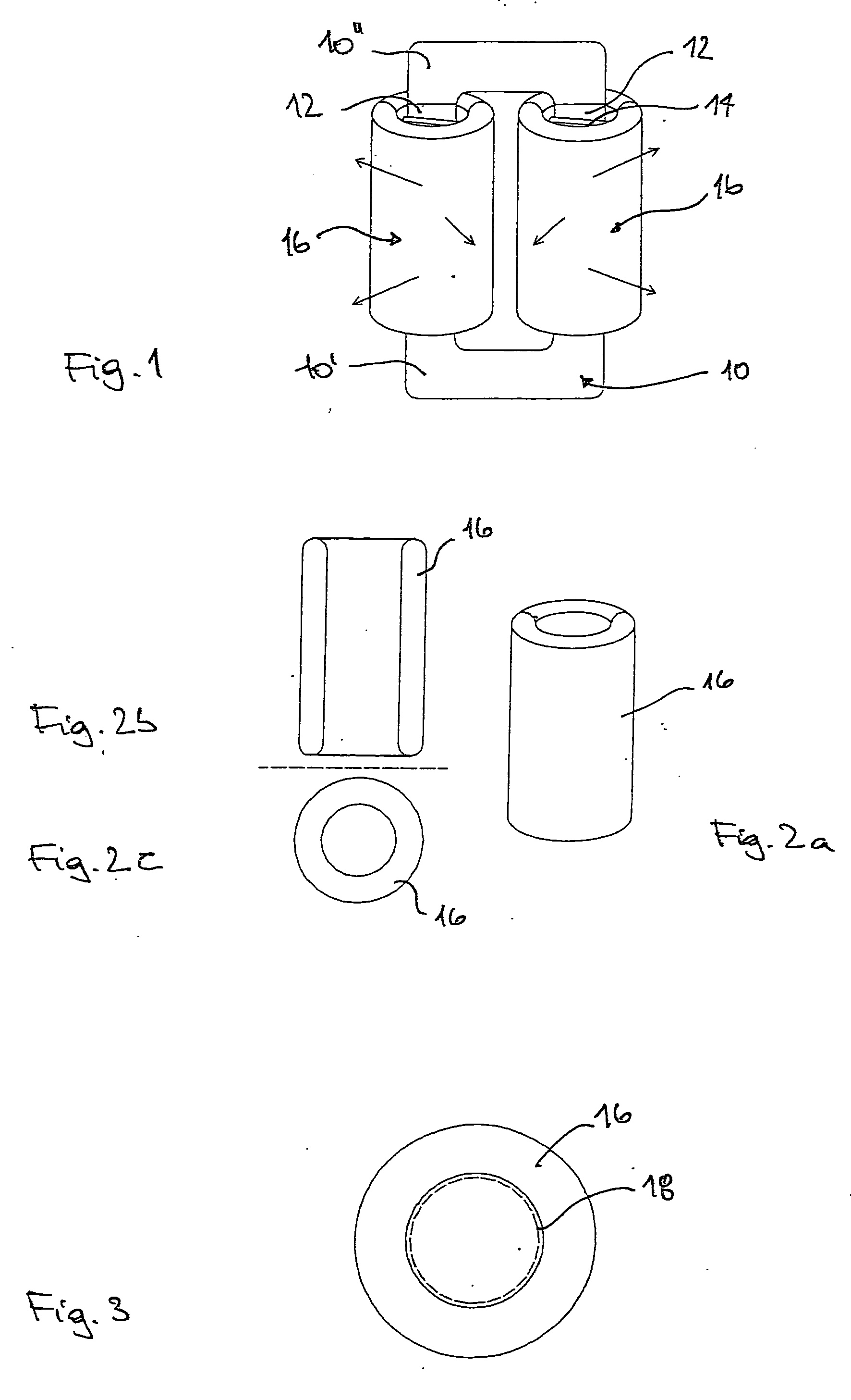
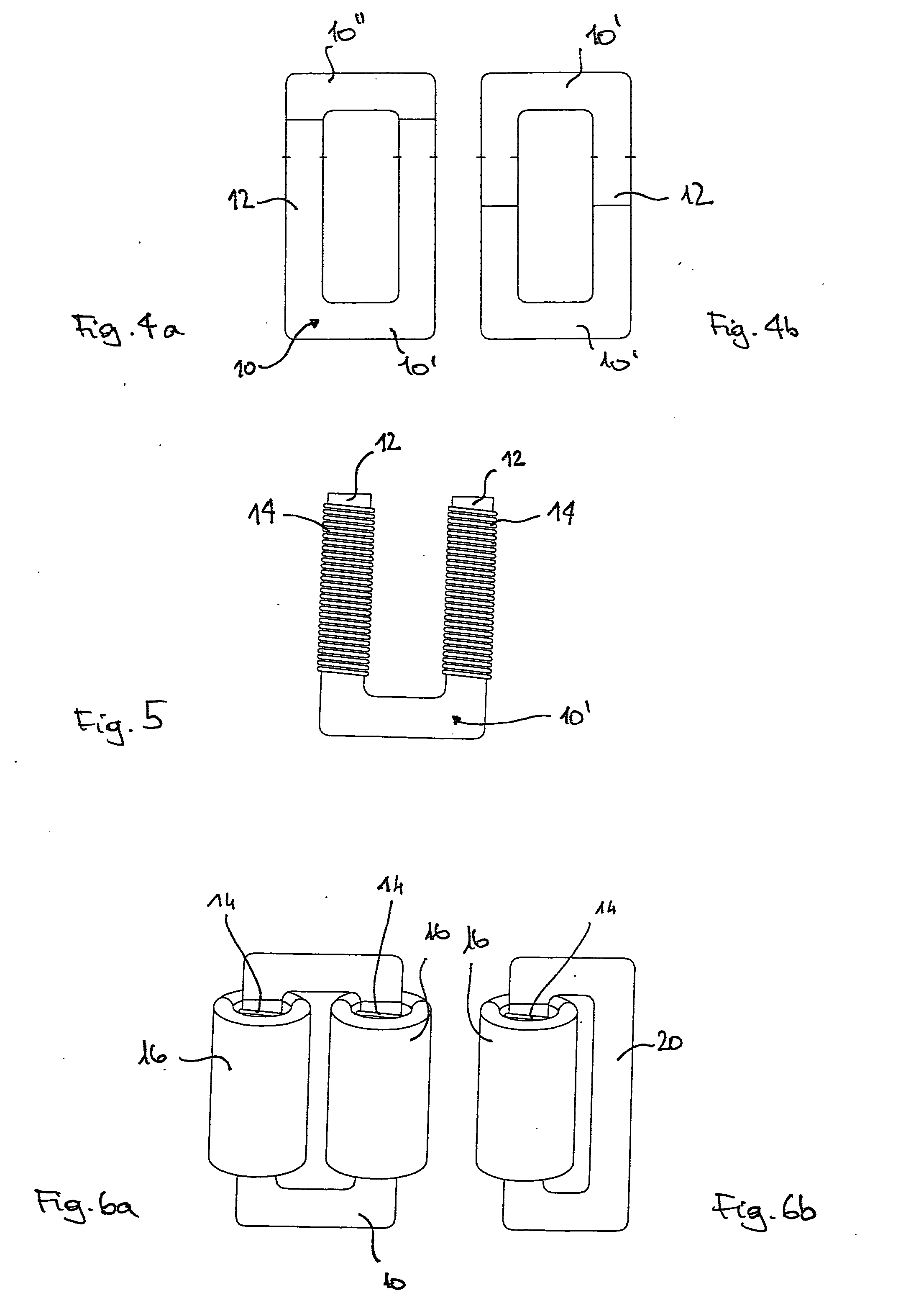
[0028]FIG. 1 shows a schematic view of a preferred embodiment of the electrodeless gas discharge lamp according to the invention. The gas discharge lamp comprises a closed core 10, having a preferably round cross-section at least in the region in which the windings are applied, which can be designed, for example, in the way of a UU-core or UI-core. In the embodiment of FIG. 1, a UI-core 10 is shown that comprises a U-piece 10′ and an I-piece 10″. The core 10 comprises two parallel straight legs 12 on which exciter windings 14 are mounted. A person skilled in the art would realize that the exact shape given to the parts of the core 10 could also be different to those shown in FIG. 1.

[0029] Each of the parallel straight legs 12 of the core 10 are led through a discharge vessel 16 that takes the form of a hollow cylindrical ring. The discharge vessel 16 is preferably made of glass. It is filled with a gaseous medium in which, due to an electric alternating field induced therein, an el...


PUM


Abstract

The invention relates to an electrodeless high frequency gas discharge lamp according to the induction principle that, as a result of its design and construction, shows particularly low electromagnetic interference with a simultaneous increase in light efficiency. The gas discharge lamp according to the invention owes these advantageous properties on the one hand to the high coupling factor between the discharge current and the exciting current and, on the other hand, to the essentially homogeneous field conditions in the discharge vessel, which has been achieved by designing the discharge vessel to take the form of a hollow cylindrical ring which is seated directly over the exciter winding that extends over the entire length of the discharge vessel on a fully-closed, highly-permeable ferrite core.

Description

FIELD OF THE INVENTION [0001] The invention relates to an electrodeless gas discharge lamp having a discharge vessel that is filled with a gaseous medium under highly reduced pressure (<10−3. . . 10−6 bar) and having an induction coil that comprises a closed core made of magnetic material onto which an exciter winding is mounted, the exciter winding being fed by a high frequency oscillator. The closed core partly extends through a tubular channel within the discharge vessel. This kind of lamp is known from DE 30 08 535 C2. BACKGROUND OF THE INVENTION [0002] In electrodeless gas discharge lamps that operate according to the induction principle, an electric discharge or a plasma is generated and maintained in a discharge vessel or lamp envelope by means of a high frequency alternating electromagnetic field. The transformation of electric energy into light is achieved by the excitation of atoms in the plasma discharge by means of impact ionization in the electric field. In contrast ...

Claims


Application Information

Patent Timeline
Patent Type & Authority Applications(United States)
IPC IPC(8): H01J17/26
CPCH01J65/048
Inventor WEGER, ROBERT
Owner MINEBEA CO LTD
Why Eureka
Try Eureka