Carbon dioxide recovery from flue gas and the like

a technology of flue gas and carbon dioxide, applied in the field of carbon dioxide recovery, can solve the problems of high transportation cost, high waste, and accounting for nearly 75% of the operating cos

Inactive Publication Date: 2007-06-28
PRAXAIR TECH INC
View PDF11 Cites 61 Cited by
  • Summary
  • Abstract
  • Description
  • Claims
  • Application Information

AI Technical Summary

Benefits of technology

[0049] The practice of the present invention affords several significant advantages. In particular, less energy is required, per unit of carbon dioxide treated, for the heating and evaporating that are inherent in the process. This is believed to be due to the lower amount of energy required to evaporate the organic component and the lessened amount of water present that needs to be evaporated. Also, the circulation rate of absorbent solutions containing the organic component of the present invention can remain the same as the circulation rate of the absorbent solution without the organic component.

Problems solved by technology

Typically, liquid CO2 is produced at a central plant and then transported to users that could be hundreds of miles away, thereby incurring high transportation costs.
This is highly wasteful because of the significant energy expended in compressing the nitrogen that is also present.
Steam consumed in the regeneration step is the most dominant cost component, typically accounting for nearly 75% of the operating cost.
Typically, flue gases contain significant amounts of oxygen (>2%), which can cause degradation of the amine(s) and other components of the absorbent.
The degradation byproducts lead to corrosion problems as well as cause significant deterioration in the overall performance, such as a drop in CO2 recovery.

Method used


Image

  • Carbon dioxide recovery from flue gas and the like

Examples


Embodiment Construction

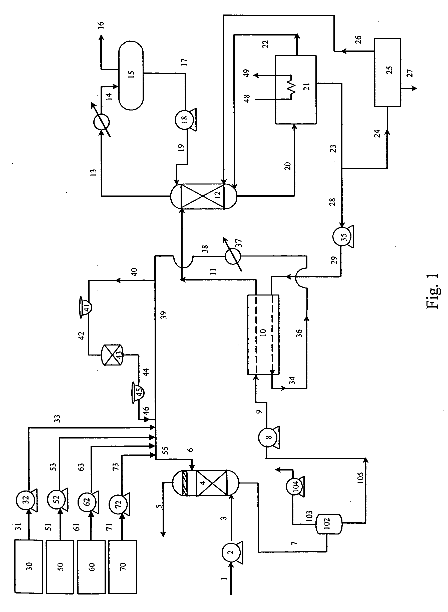
[0020] Referring to the Figure, feed gas mixture 1, which typically has been cooled and treated for the reduction of particulates and other impurities such as sulfur oxides (SOx) and nitrogen oxides (NOx), is passed to compressor or blower 2 wherein it is compressed to a pressure generally within the range of from 14.7 to 30 pounds per square inch absolute (psia). Feed gas mixture 1 generally contains from 2 to 50 mole percent carbon dioxide as the absorbate, and typically has a carbon dioxide concentration within the range of from 3 to 25 mole percent. Feed gas mixture 1 also contains oxygen in a concentration generally within the range of from less than 1 to about 18 mole percent. Feed gas mixture 1 may also contain one or more other components such as trace hydrocarbons, nitrogen, carbon monoxide, water vapor, sulfur oxides, nitrogen oxides and particulates. A preferred feed gas mixture is flue gas, by which is meant gas obtained upon the complete or partial combustion of hydroca...


PUM

PropertyMeasurementUnit
temperatureaaaaaaaaaa
temperaturesaaaaaaaaaa

Abstract

Carbon dioxide is recovered in concentrated form from a gas feed stream also containing oxygen by absorbing carbon dioxide and oxygen into an amine solution that also contains another organic component, removing oxygen, and recovering carbon dioxide from the absorbent.

Description

FIELD OF THE INVENTION [0001] This invention relates generally to the recovery of carbon dioxide and, more particularly, to the recovery of carbon dioxide from a feed mixture which also contains oxygen. BACKGROUND OF THE INVENTION [0002] Carbon dioxide is produced from feed streams with high CO2 purity (which term as used herein means having a carbon dioxide content of ≧95%), where such streams are available, using distillation technology. Examples of such sources include ammonia and hydrogen plant off gases, fermentation sources and naturally-occurring gases in CO2-rich wells. Typically, liquid CO2 is produced at a central plant and then transported to users that could be hundreds of miles away, thereby incurring high transportation costs. The lack of sources with high concentrations of carbon dioxide and their distance from customers provides motivation to recover CO2 from low concentration sources, which are generally available closer to customer sites. Predominant examples of su...

Claims


Application Information

Patent Timeline
Patent Type & Authority Applications(United States)
IPC IPC(8): B01D53/14C01B32/50
CPCB01D53/1475Y02C10/06C01B31/20B01D53/1493C01B32/50Y02P20/151Y02C20/40B01D53/14
Inventor CHAKRAVARTI, SHRIKARBURGERS, KENNETH LEROYGUPTA, AMITABHWILLIAMS, WILLIAM ROBERT
Owner PRAXAIR TECH INC
Why Eureka
Try Eureka