Tri-excluded WUCS glass fiber reinforced plastic composite articles and methods for making such articles

a technology of glass fiber reinforced plastic and composite articles, which is applied in the direction of textiles and papermaking, transportation and packaging, textiles, etc., can solve the problems of less suitable products for forming composite products, products generally unsuitable for articles subjected to bending, and the thickness and length of wood fiber and strand typically utilized in producing osb products are generally less suitable for products, so as to achieve a reduced or optimal level of incorporation, improve the performance of products, and effectively enhan

Inactive Publication Date: 2007-06-28
OCV INTELLECTUAL CAPITAL LLC
View PDF45 Cites 31 Cited by
  • Summary
  • Abstract
  • Description
  • Claims
  • Application Information

AI Technical Summary

Benefits of technology

[0015] It is an advantage of the present invention that the inclusion of additives to the size composition permits for the customization of product-specific sizing compositions tailored to achieve desired physical or structural attributes.
[0016] It is another advantage of the present invention that utilizing the reinforcing fibers as a carrier for desired additives may result in an overall improvement in the performance of the products formed from the additive-sized reinforcement fibers.
[0017] It is yet another advantage of the present invention that incorporating additives into the size composition and onto the reinforcement fibers may aid the dispersion of the additives substantially evenly throughout the polymer matrix.
[0018] It is a further advantage of the present invention that by applying desired additives directly to the reinforcement fibers, the additives can be expected to more effectively enhance the interface between the resin and the surface of the reinforcement fibers.
[0019] It is also an advantage of the invention that because the additives are added with the size composition directly onto the reinforcement fiber, they may be incorporated at a reduced or optimal level.
[0020] It is a feature of the present invention that the application of desired additives to the reinforcing fiber with the sizing composition may result in a reduction in the amount of wasted additives and manufacturing costs.

Problems solved by technology

Although this process is generally suitable for forming large planar sheets, it is less suitable for forming composite products that have complex profiles and / or otherwise formed portions.
In addition, wood fiber and strand thickness and length typically utilized in producing OSB products are generally less suitable for products intended for applications in which mechanical forces must be transmitted more uniformly throughout the composite product.
Indeed, the variations in the diameter and length of the wood fibers incorporated into the OSB products tend to produce regions of high pressure and low pressure that render such products generally unsuitable for articles subjected to bending stresses.
The structural limitations associated with particleboard, particularly its reduced strength relative to corresponding thicknesses of OSB and plywood products, its tendency to absorb water, and its increased density render it unsuitable for many applications, particularly exposed applications or those in which significant loads are anticipated.
This limitation can result in an acute disadvantage in systems that obtain waste wood from many different sources.
The use of these isocyanate binding agents may also raise environmental and workplace safety issues.
These compositions also tend to exhibit only limited moisture protection and do not tend to exhibit uniform strength characteristics throughout their load bearing portions.
While the products produced by incorporating one or more plastics may exhibit improved moisture resistance, such articles continue to suffer from either the strength limitations referenced above or by requiring an intricate and complex forming process.
Additionally, the conventional methods which utilize wood fibers in some capacity to form a finished composite article do not tend to utilize the waste wood supply in any substantive manner, with portions of the waste wood typically being incinerated, used as fuel in an electrical cogeneration facility or buried in a landfill.

Method used


Image

  • Tri-excluded WUCS glass fiber reinforced plastic composite articles and methods for making such articles
  • Tri-excluded WUCS glass fiber reinforced plastic composite articles and methods for making such articles
  • Tri-excluded WUCS glass fiber reinforced plastic composite articles and methods for making such articles

Examples


first embodiment

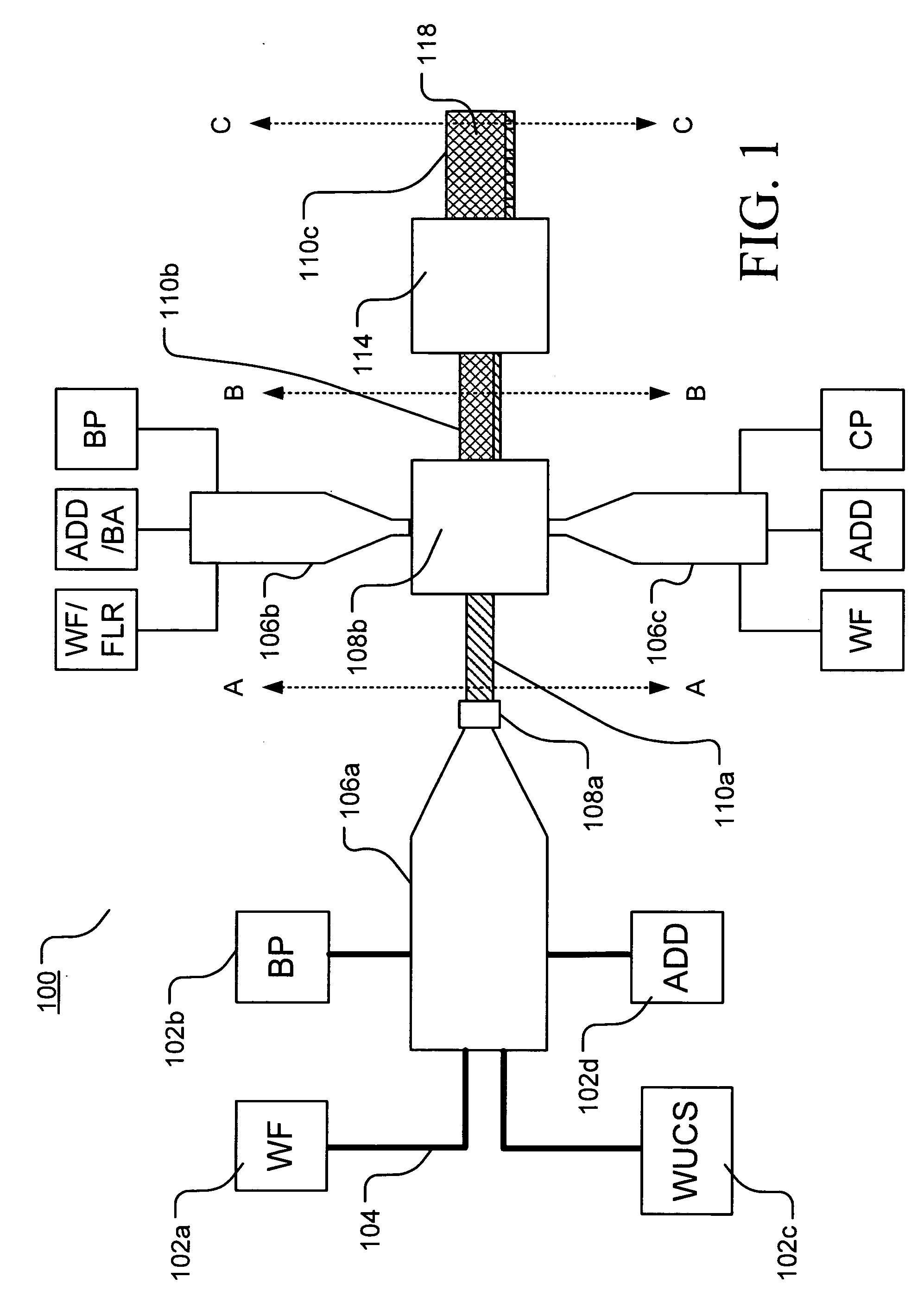
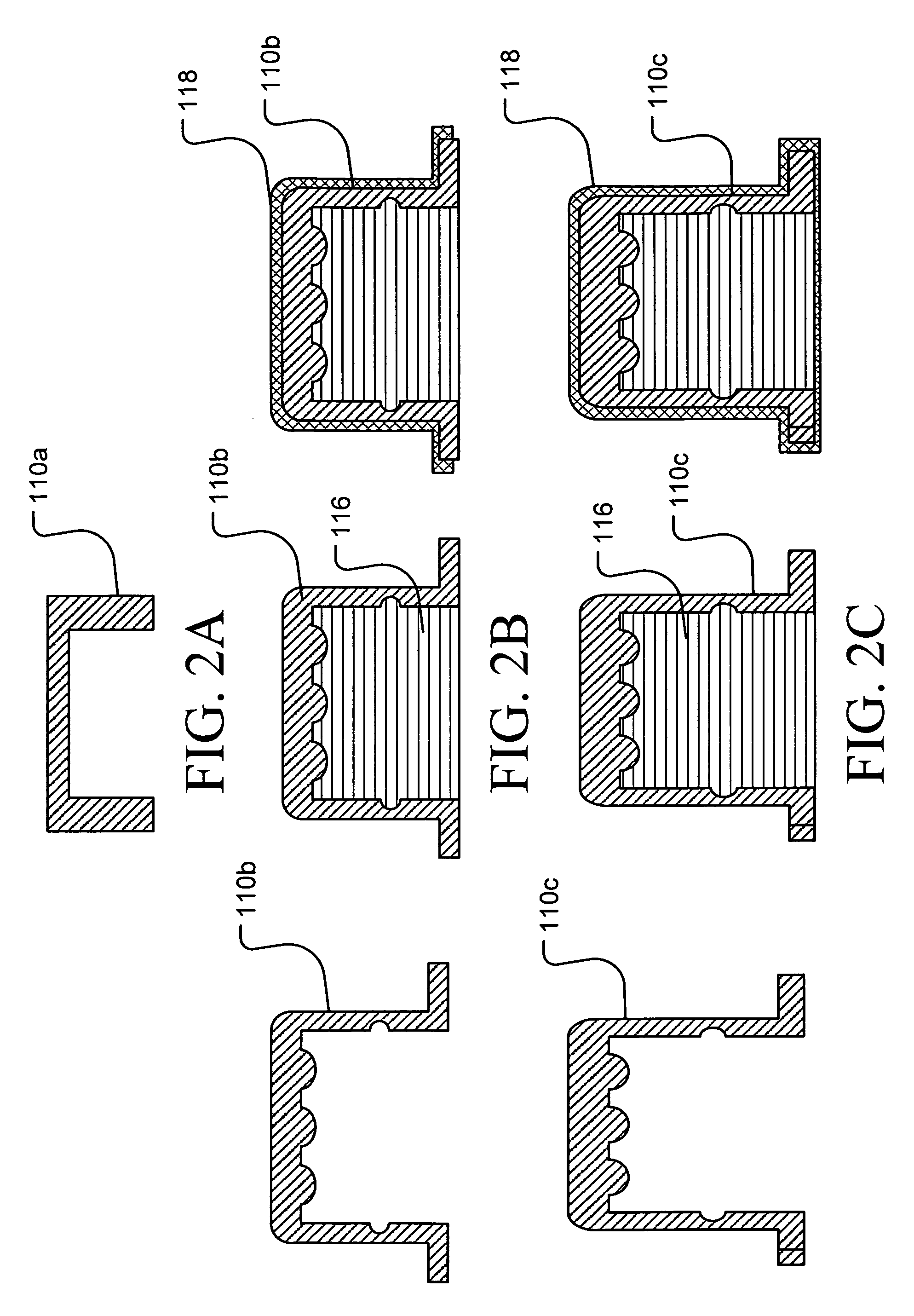
[0073] Illustrated in FIG. 1 is an example of a manufacturing line according to an embodiment of the invention in which various components such as wood fibers (WF) 102a, base polymers (BP) 102b, wet use chopped strand fiberglass (WUCS) 102c and other additives (ADD) 102d are provided through feed lines 104 to a blender / extruder mechanism 106a. Similar blender / extruder mechanisms 106b and 106c may be used to prepare one or more additional compositions for combination with the primary structure or initial form 110a as it is extruded from die 108 or shortly thereafter to fabricate a composite article. The other compositions may be prepared in the blender / extruder mechanisms 106b, 106c to form uniform mixtures having a suitable temperature and viscosity and then extruding the mixture through one or more dies included in apparatus 112 to form an initial form 110a. An example of a cross-section of initial form 110a along plane A-A is illustrated in FIG. 2A.

[0074] As suggested in FIG. 1, ...

second embodiment

[0077] Illustrated in FIG. 3 is an example of a manufacturing line according to another embodiment of the invention in which various components such as wood fibers (WF) 202a, binders and / or polymers (BP) 202b, fiberglass reinforcement (WUCS) 202c and other additives (ADD) 202d are provided through feed lines 204 to a blender / extruder mechanism 206. The various components are combined in the blender / extruder mechanism 206 to form a uniform mixture having a suitable temperature and viscosity and then extruding the mixture through a die 208 to form an initial form 210a. An example of a cross-section of initial form 210a along plane A-A is illustrated in FIG. 4A.

[0078] If desired, the initial form 210a may then be subjected to additional heating and / or forming operations in unit 212 to modify the initial form an produce an intermediate form 210b having a more complex cross-sectional profile. An example of an intermediate form 210b is illustrated in FIG. 4B. As illustrated in FIG. 3, a ...

third embodiment

[0080] Illustrated in FIG. 5 is an example of a manufacturing line according to another embodiment of the invention in which various components such as wood fibers (WF) 302a, binders and / or polymers (BP) 302b, fiberglass (WUCS) 302c and other additives (ADD) 302d are provided through feed lines 304 to a blender / extruder mechanism 306a. The various components are combined in the blender / extruder mechanism 306a in different proportions to form at least two separate and distinct compositions at suitable temperatures and viscosities for extrusion processing. The two compositions are then extruded through a die 308a to form an initial form 310a in which a first composition 314 forms a primary structural frame for the final product with a second composition 316 at least partially filling recesses defined in the primary structural frame form. An example of a cross-section of initial form 310a along plane A-A is illustrated in FIG. 6A in which the first composition 314 is extruded as a clos...


PUM

PropertyMeasurementUnit
weightaaaaaaaaaa
roughnessaaaaaaaaaa
abrasion resistanceaaaaaaaaaa

Abstract

Disclosed are a series of composite polymer composite structures formed by the coextrusion of at least two distinct polymeric components. A first polymeric component includes a structural composition and a second polymeric component includes a coating composition. The primary structural frame formed from the structural composition includes at least one longitudinal recess. These recesses may be filled with a third polymeric composition that may include wood byproducts and/or a blowing agent. The first polymeric component may include reinforcing fibers at least partially coated with a size composition that includes a film forming agent, a lubricant, one or more additives, and first and second coupling agents. The additives may be chosen to achieve selective or desired properties in the end product. The inclusion of additives to the reinforcing fiber enhances the fiber reinforcements and enables the production of reinforced composite articles having a desired combination of size, strength, appearance, and/or functionality.

Description

CROSS REFERENCE TO RELATED APPLICATIONS [0001] This application is a Continuation-in-Part of U.S. patent application Ser. No. 11 / 311,749 entitled “Tri-Extruded WUCS Glass Fiber Reinforced Plastic Composite Articles And Methods For Making Such Articles” filed Dec. 19, 2005, the entire content of which is expressly incorporated herein by reference in its entirety.TECHNICAL FIELD AND INDUSTRIAL APPLICABILITY OF THE INVENTION [0002] The present invention relates to tri-extruded composite articles, and more particularly, to a sizing composition for reinforcing fibers used in tri-extruded reinforced composite articles where the sizing composition includes additives to achieve desired physical or structural attributes. BACKGROUND OF THE INVENTION [0003] Wood fibers, especially fibers from waste wood generated during the production of dimensional lumber or the milling or shaping of wood substrates, in combination with one or more polymeric adhesives, have long been used in the production of...

Claims


Application Information

Patent Timeline
Patent Type & Authority Applications(United States)
IPC IPC(8): D04H13/00B29C48/06B29C48/07B29C48/11B29C48/12
CPCB29C47/0004B29C47/0023B29C47/0052B29C47/025B29C47/065B29C47/128B29K2105/06C03C25/26C08J5/08B29C48/022B29C48/09B29C48/0016B29C48/154B29C48/21B29C48/304Y10T428/249924B29C48/12B29C48/06B29C48/11B29C48/07
Inventor MCGRATH, RALPH D.STRAIT, MICHAEL A.GUIGLEY, KEVIN S.WALDEN, DOUGLAS H.WAGNER, TERESA L.DIWANJI, ASHISH
Owner OCV INTELLECTUAL CAPITAL LLC
Why Eureka
Try Eureka