Balloon catheter

Inactive Publication Date: 2007-06-28
TORAY IND INC
View PDF30 Cites 177 Cited by
  • Summary
  • Abstract
  • Description
  • Claims
  • Application Information

AI Technical Summary

Benefits of technology

[0026] This invention provides a balloon ablation catheter free from the possibility that the counter electrode generates heat, since both the high-frequency electrodes are disposed in the balloon, to get rid of the conventional counter electrode disposed outside a patient's body.
[0027] Since both the high-frequency electrodes are placed in the balloon made of an electrically highly resistant material, it does not happen that high-frequency electrical current flows to the tip of the guide wire during ablation. Therefore, the invention provides a balloon ablation catheter, in which the ablation of a blood vessel or tissue other than the target lesion site by the heating at the tip of the guide wire does not occur.
[0028] If the surface areas of both the high-frequency electrodes are 20 mm2 or more respectively, and in addition, preferably, if the shortest distance between the electrodes is 1 mm or more, then the invention provides a balloon ablation catheter that allows the temperature in the balloon to be raised without causing the liquid in the balloon to boil.
[0029] If a temperature sensor is disposed inside or on the outer surface of the balloon, the invention provides a balloon ablation catheter that allows the temperature of the inside or surface of the balloon to be accurately detected.
[0030] If a spacer is installed between both the high-frequency electrodes, it does not happen that the high-frequency electrodes approach each other during the ins

Problems solved by technology

However, in the case of the balloon ablation catheter using the counter electrode plate, the high-frequency electrical current during ablation may cause the counter electrode plate 54 attached to the patient's body surface to generate heat.
However, the medical system described in patent document 2 merely causes general necrosis of the cells at and

Method used


Image

  • Balloon catheter
  • Balloon catheter
  • Balloon catheter

Examples


example 1

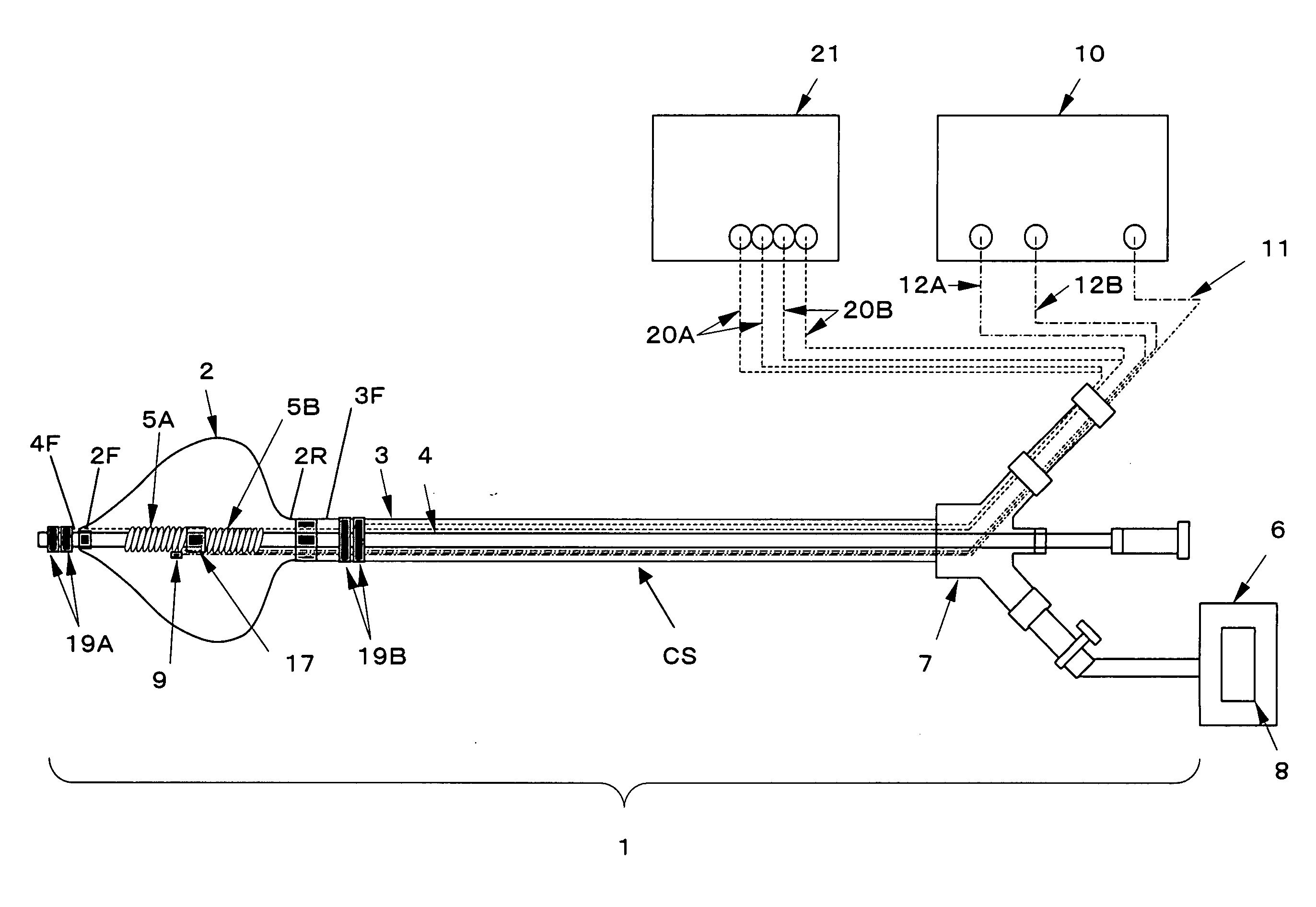
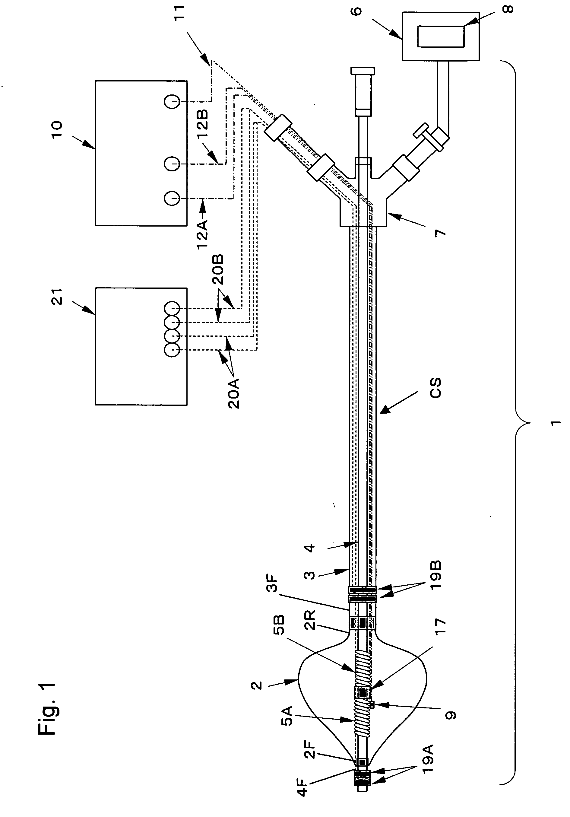
[0145] A balloon 2 formed like a tapered cone with a length of 30 mm from the front end to the rear end of the balloon 2, with the largest outer diameter of 30 mm on the rear end side and a film thickness of 160 μm was produced as described below.

[0146] A balloon glass mold having a surface corresponding to a desired balloon form was dipped in 13% polyurethane solution, and the coated mold was heated to evaporate the solvent, to form a urethane polymer film on the surface of the mold as the balloon 2 by a dipping method.

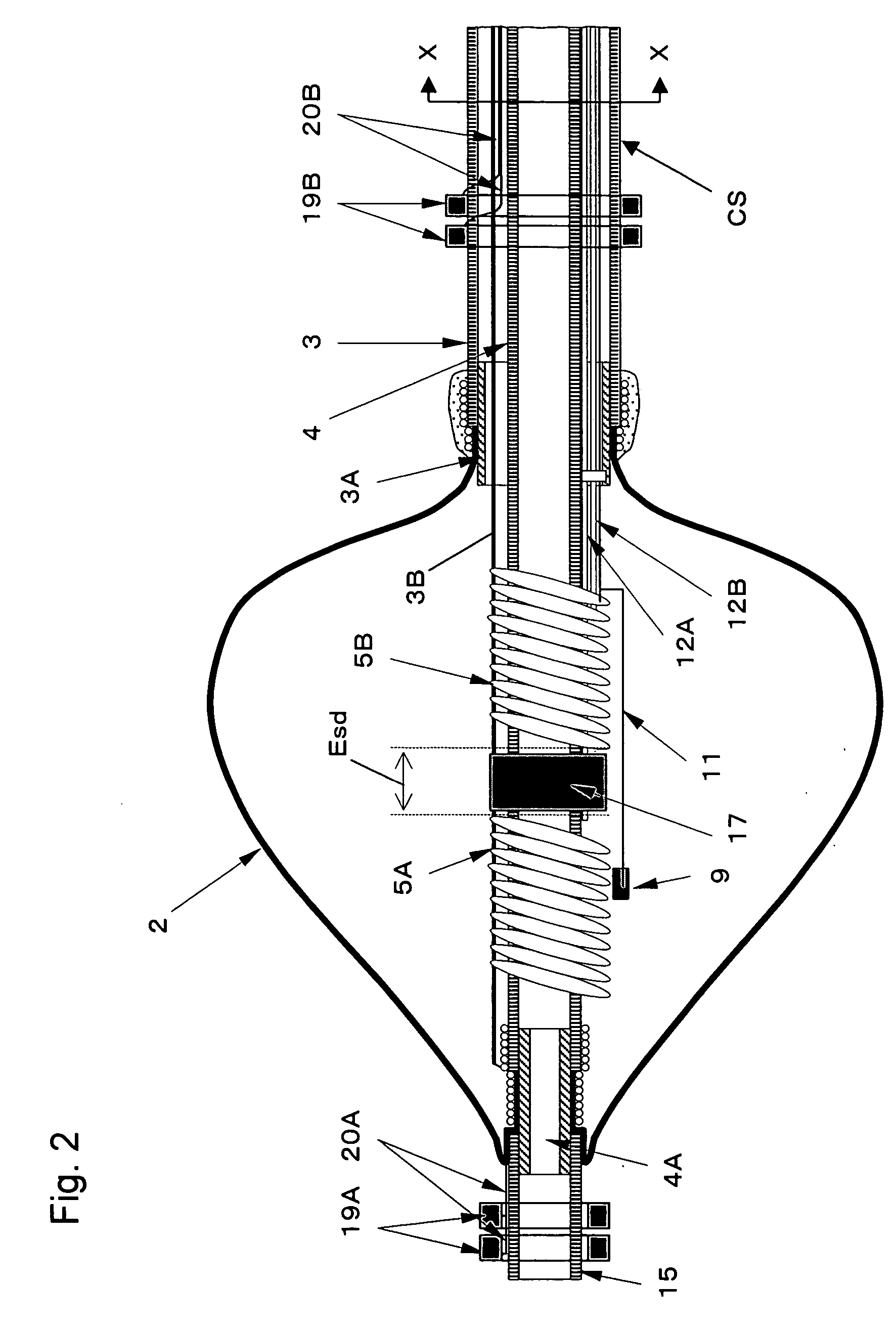
[0147] As the outer cylindrical shaft 3 of the catheter 1, a 30% barium sulfate-containing PVC tube with an outer diameter of 12Fr, an inner diameter of 2.7 mm and an overall length of 800 mm was prepared. As the metallic pipe 3A, a stainless steel pipe with a diameter of 2.8 mm and a length of 7 mm, with its outer surface finished by sandblasting, was prepared. The metallic pipe 3A was partially inserted and fitted into the front end of the outer cylindrical shaft...

example 2

[0163] A catheter identical with the ablation catheter of Example 1 except that a metallic guide wire was inserted through the hollow portion of the inner cylindrical shaft 4, was prepared. This catheter is hereinafter called the ablation catheter of Example 2. The heat generation of the metallic guide wire used in the ablation catheter of Example 2 was examined.

[0164] The ablation catheter of Example 2 was immersed in a water tank filled with 37° C. physiological saline. The high-frequency power supply leads 12A and 12B were connected with the high-frequency power supply apparatus 10. Into the balloon 2, a liquid obtained by diluting a contrast medium (ioxaglic acid injection: trade name Hexabrix 320) to 50% using physiological saline was injected to inflate the balloon 2 to such a state that the largest outer diameter on the rear end side of the balloon 2 became 30 mm.

[0165] As the guide wire, a SUS304 wire having a diameter of 0.025 inch (about 0.6 mm) and a length of 1500 mm w...

example 3

[0170] A catheter identical with the ablation catheter of Example 1 except that the lengths of the high-frequency electrodes 5A and 5B in the axial direction of the catheter 1 were 1 mm respectively, was prepared. The surface areas of SA and SB of the high-frequency electrodes 5A and 5B in this catheter were about 20 mm2 respectively. This catheter is hereinafter called the ablation catheter of Example 3.

[0171] The ablation catheters of Comparative Example 2 and Examples 1 and 3 were respectively immersed in a water tank filled with 37° C. physiological saline, and in each of the catheters, the high-frequency power supply leads 12A and 12B were connected with the high-frequency power supply apparatus 10. In each of the catheters, a liquid obtained by diluting a contrast medium (ioxaglic. acid injection: trade name Hexabrix 320) to 50% using physiological saline was injected into the balloon 2, to inflate the balloon 2 to such a state that the largest outer diameter on the rear end ...


PUM


Abstract

A balloon catheter in which a high-frequency current is supplied between electrodes spaced in a balloon, the liquid in the balloon is heated, and the heat conducted through the balloon ablates the organism tissue in contact with the balloon, characterized in that the area of the surface of each electrode is 20 mm2 or more or a potential detecting electrode for detecting the potential at an abrasion portion is disposed outside the balloon and in a position at least before or behind the balloon.

Description

TECHNICAL FIELD [0001] The present invention relates to a balloon catheter. In more detail, the invention relates to a balloon catheter to be inserted into a patient's body, for keeping the balloon of the catheter in contact with a target lesion site with an intention to heat the target lesion site, through the balloon, by the heat of the liquid internally filling the balloon heated by the high-frequency dielectric heating and the Joule heating respectively caused by high-frequency current, in order to perform the ablation of the target lesion site by means of the heat. This catheter is called a balloon ablation catheter. BACKGROUND ART [0002] Ablation catheters for use in treating of cardiac arrhythmia are developed. Patent document 1 describes a balloon ablation catheter to electrically isolate pulmonary veins for treating of arrhythmia. In the case where such a balloon ablation catheter is used for electrically isolating pulmonary veins, as shown in FIG. 8, an inflatable / deflatab...

Claims


Application Information

Patent Timeline
IPC IPC(8): A61B18/04A61B18/14
CPCA61B18/04A61B18/1492A61B2018/046A61B2018/00702A61B2018/00791A61B2018/0022A61M29/02
Inventor MATSUKUMA, AKINORIYAMAZAKI, YOSHIHARU
Owner TORAY IND INC
Why Eureka
Try Eureka