
Method of forming a glass melt

Active Publication Date: 2007-07-05
CORNING INC
View PDF44 Cites 25 Cited by
  • Summary
  • Abstract
  • Description
  • Claims
  • Application Information

AI Technical Summary

Benefits of technology

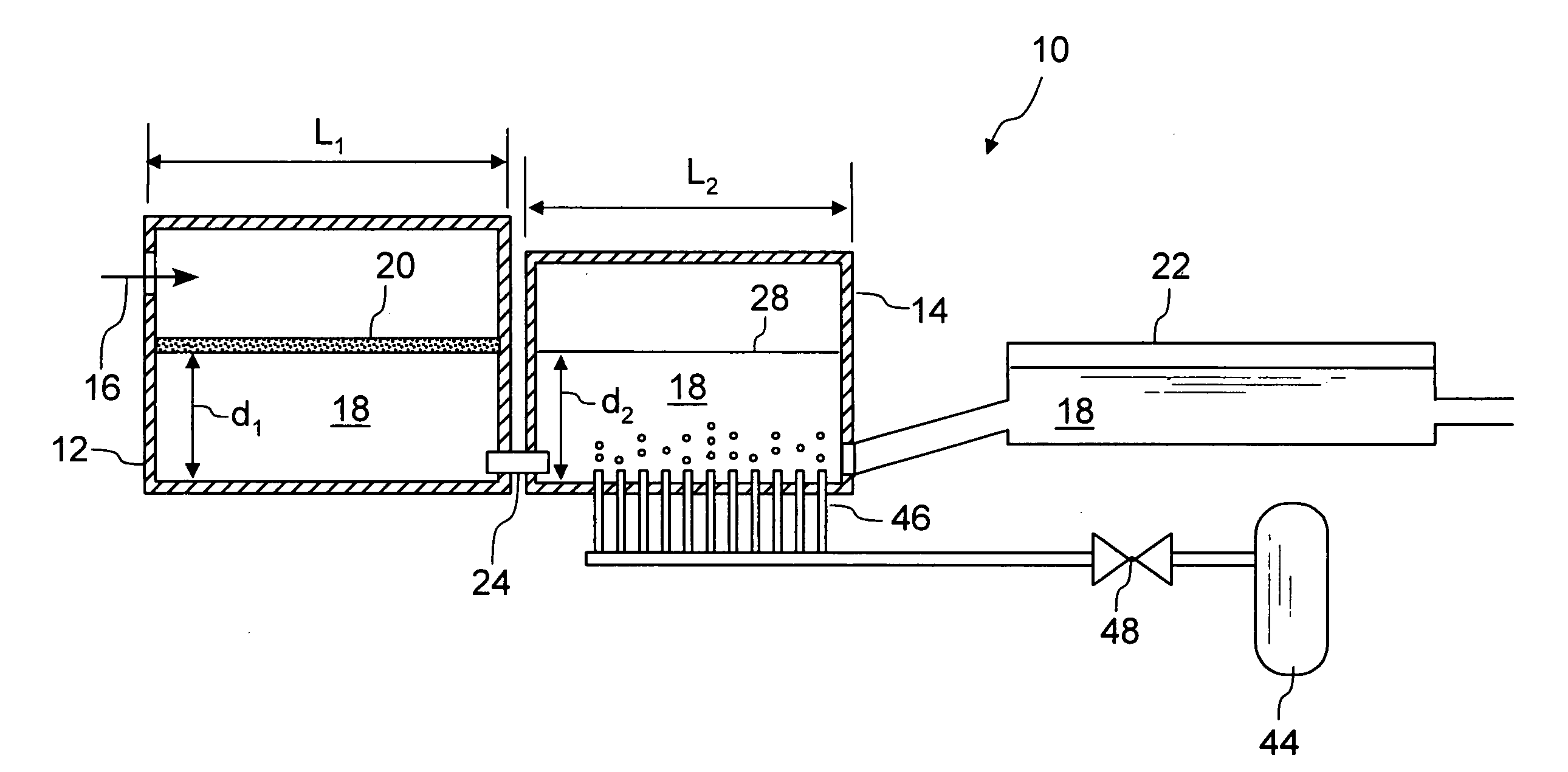
[0014] Preferably, the melt rate of the second furnace is between about 50% and 90% of the melt rate of the first furnace. The glass melt within the second melting furnace may also be mechanically agitated. Mechanical agitation may be performed by, for example, bubbling a gas through the glass melt in the second melting furnace. Oxygen is one suitable gas, but air and inert gases are also acceptable alternatives. Advantageously, oxygen may be used to recharge or reload multivalent fining agents within the melt. Reloading the fining agent with oxygen is most effective when the temperature of the glass melt is lowered during the reloading.
[0015] In one particular embodiment, the partial pressure of hydrogen in an atmosphere in contact with the refractory metal transfer tube may be controlled so as to promote vigorous boiling of the glass melt passing through the transfer tube. This can be accomplished by lowering the partial pressure of hydrogen in the atmosphere outside the tube such that it is lower than the partial pressure of hydrogen within the glass melt.

Problems solved by technology

These solid inclusions can become solid defects in the finished glass.
The subsequent poor efficiency of the burners means that most of the energy required to form the melt is provided by Joule heating from electrodes submerged below the free surface of the melt.
The resulting relatively high levels of electric power shortens electrode life and leads to frequent melter repairs.
In the case of the cross wall, both sides of the cross wall are hot and generally corrosion of the wall by the glass is relatively fast.
Thus, process life is short.
Melting effectiveness ends when the top of the cross wall is breached or when internal cooling fails, releasing cooling water directly (and explosively) into the glass melt.
Furthermore, if the cross wall is constructed of fused zirconia refractory, the electrical resistivity of the cross wall will be low, and both faces will be hot.
Some of the electric current used to heat the glass bath may pass through the cross wall, heating it independently and potentially causing failure of the wall or formation of zirconia inclusions in the melt.
Generally, cross walls are effective for limited periods of time but represent a life-limiting part of a glass melting process.
Such large increases in the dimensions of the melting furnace lead to increased capital and operating expenses, and, because the number of electrodes (typically tin oxide) would necessarily increase, may also result in raising the amount of tin oxide in the glass to levels where Cassiterite devitrification of the melt can occur.
This allows the walls to have exterior cooling but creates a significant unheated area within the melter where the glass can lose temperature as it passes from the first zone to the second zone.
In addition, refractory throat covers will wear away to the glass level, ultimately allowing the foam layer to pass through from the first to the second zone.
A throat leak can cause shutdown of the process altogether.
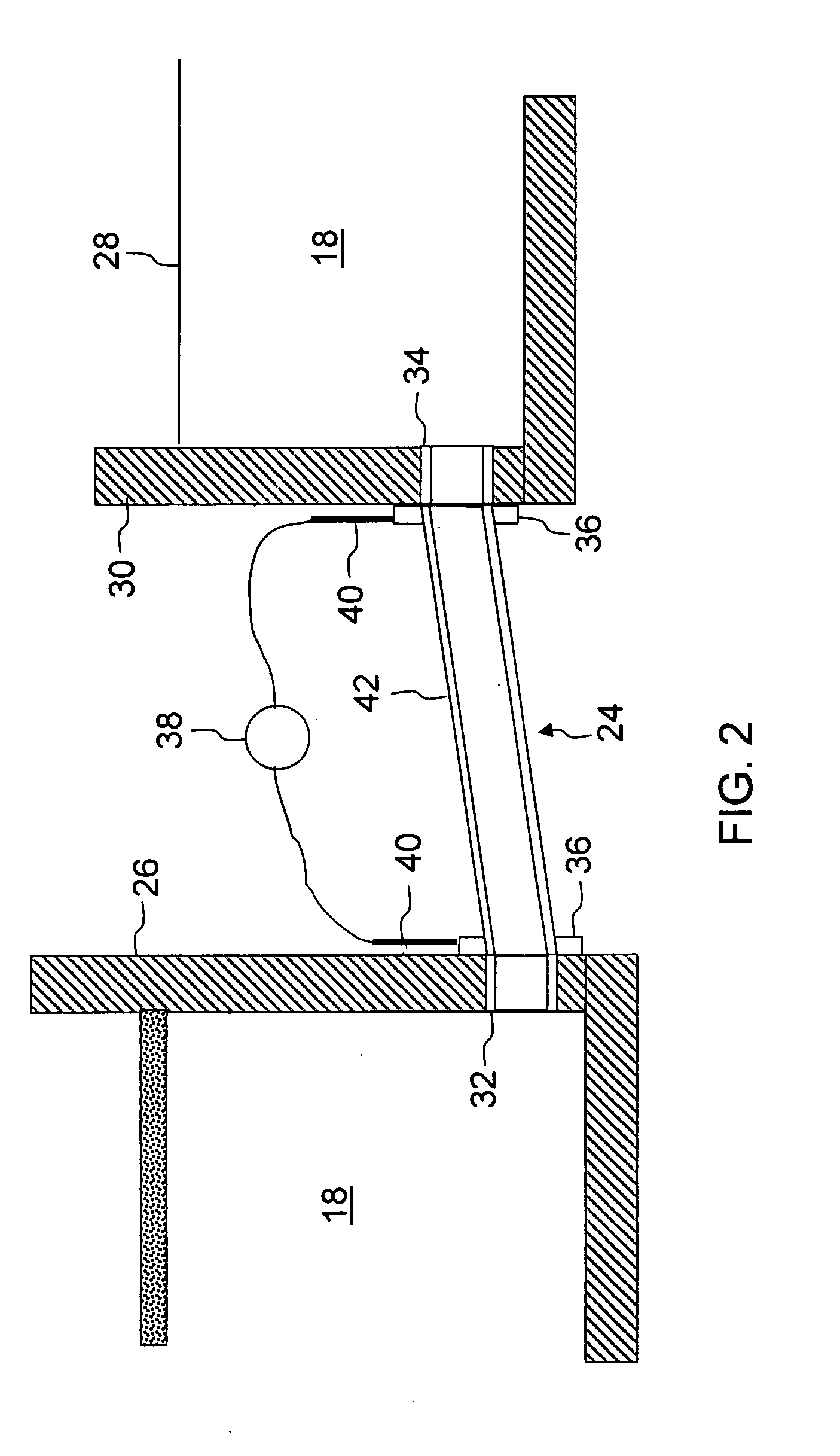
Heating the connecting tube within the first melting furnace is may be performed, but is generally unnecessary.

Method used


Image

  • Method of forming a glass melt
  • Method of forming a glass melt
  • Method of forming a glass melt

Examples


Embodiment Construction

[0022] In the following detailed description, for purposes of explanation and not limitation, example embodiments disclosing specific details are set forth to provide a thorough understanding of the present invention. However, it will be apparent to one having ordinary skill in the art, having had the benefit of the present disclosure, that the present invention may be practiced in other embodiments that depart from the specific details disclosed herein. Moreover, descriptions of well-known devices, methods and materials may be omitted so as not to obscure the description of the present invention. Finally, wherever applicable, like reference numerals refer to like elements.

[0023] In a conventional glass making process raw feed materials are heated in a furnace (melter) to form a viscous mass, or glass melt. Furnaces are generally constructed from non-metallic refractory blocks comprised of burned flint clay, sillimanite, zircon or other refractory material. The feed materials may b...


PUM

PropertyMeasurementUnit
Fractionaaaaaaaaaa
Fractionaaaaaaaaaa
Fractionaaaaaaaaaa

Abstract

A method of forming a glass melt including heating a glass feed material in a first melting furnace to form a glass melt, flowing the glass melt into a second melting furnace through a refractory metal connecting tube, and further heating the glass melt in the second melting furnace. The refractory metal connecting tube is heated to prevent the molten glass from excessive cooling, and to ensure that the glass melt entering the second melting furnace is equal to or greater than the temperature of the glass melt in the second melting furnace. An apparatus for performing the method is also disclosed.

Description

BACKGROUND OF THE INVENTION [0001] 1. Field of the Invention [0002] This invention is directed to a method of forming a glass melt, and in particular forming a glass melt utilizing a multi-zone melter. [0003] 2. Technical Background [0004] Liquid crystal displays (LCDs) are passive flat panel displays which depend upon external sources of light for illumination. Alkali-free alumino-silicate glasses are commonly used for LCD sheet glass applications. This family of glasses tends to create a stable foam layer on the surface of the melting furnace (melter) in a location where the batch (glass feed) materials are filled. The foam layer contains solid silica inclusions that can become either solid “stone” or clear “knot” defects in the finished glass unless they are removed prior to the glass entering the delivery system. It has been shown that this foam layer, when allowed to reach the front wall of the melter, can deliver solid inclusions via the melter exit to the glass delivery syste...

Claims


Application Information

Patent Timeline
IPC IPC(8): C03B18/22C03B5/00
CPCC03B5/04Y10S65/09C03B5/20C03B5/193C03B18/22
Inventor DEANGELIS, GILBERTJOHNSON, WILLIAM WESTONKERSTING, JOHN JERRYNOLET, DANIEL ARTHURTHOMAS, ROBERT RICHARDVERDURME, PASCAL
Owner CORNING INC
Learn More