Nanostructural Electrode and Method of Forming the Same

a nano-structural electrode and electrode technology, applied in the direction of cell components, electrochemical generators, coatings, etc., can solve the problems of affecting the use of high current of charge and discharge, destroying carbonic fragments, loss of electrical contact between, and failing to ensure the high speed of discharge and charge of batteries. , to achieve the effect of improving nano-structure, low cost and adhesion properties

Inactive Publication Date: 2007-07-05
NANOENER
View PDF6 Cites 49 Cited by
  • Summary
  • Abstract
  • Description
  • Claims
  • Application Information

AI Technical Summary

Benefits of technology

[0021] Another advantage of the present invention is to provide a unique metal current collector of an electrode with integrated active core having a porous structure received by effective deposition of a material onto the metal current collector substrate in a binder free fashion while maintaining outstanding adhesion properties.
[0022] Still another advantage of the present invention is to provide a unique method for fabricating the electrodes wherein the metal current collector presents nano-structured surface at low cost.
[0023] Still another advantage of the present invention is to provide an electrode material having an improved nano-structure which is utilized as at least cathode or anode of a fuel cell leading to low thermal stability and improved live-span.
[0024] Still another advantage ...

Problems solved by technology

This method fails to provide the electrodes for the cell having high speeds of a charge and discharge because of high electric resistance between the fragments of active substance and between the fragments and the metal current collector thereby resulting in general and common impedance of the system negatively impacting the usage of high currents of the charge and discharge.
The volumetric changes in graphite and other forms and shapes of existence of carbon at the reversible intercalation of lithium ions present another problem such as destruction of carbonic fragments and loss of an electrical contact between them.
However, all these methods fails to ensure the high speed of the discharge and the charge of the battery because to the availability of the dielectric binding and mechanical contact between the fragments.
Moreover, the presence of the binder limits the temperature interval of usage of lithium-ionic batteries, because the raise of the temperature emolliates the binding effect thereby resulting in formation of conglomerates of active material, the loss of a contact between them, distortion of an electrical field inside of an elect...

Method used


Image

  • Nanostructural Electrode and Method of Forming the Same
  • Nanostructural Electrode and Method of Forming the Same
  • Nanostructural Electrode and Method of Forming the Same

Examples


Embodiment Construction

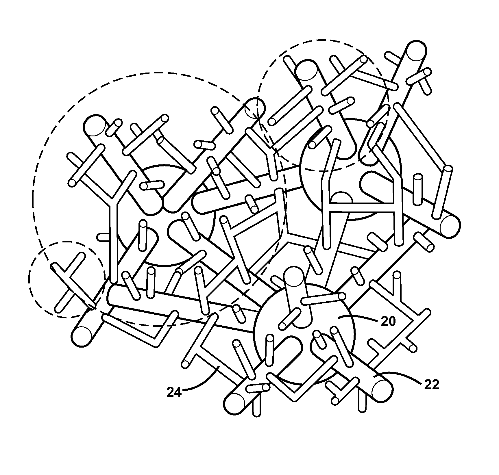
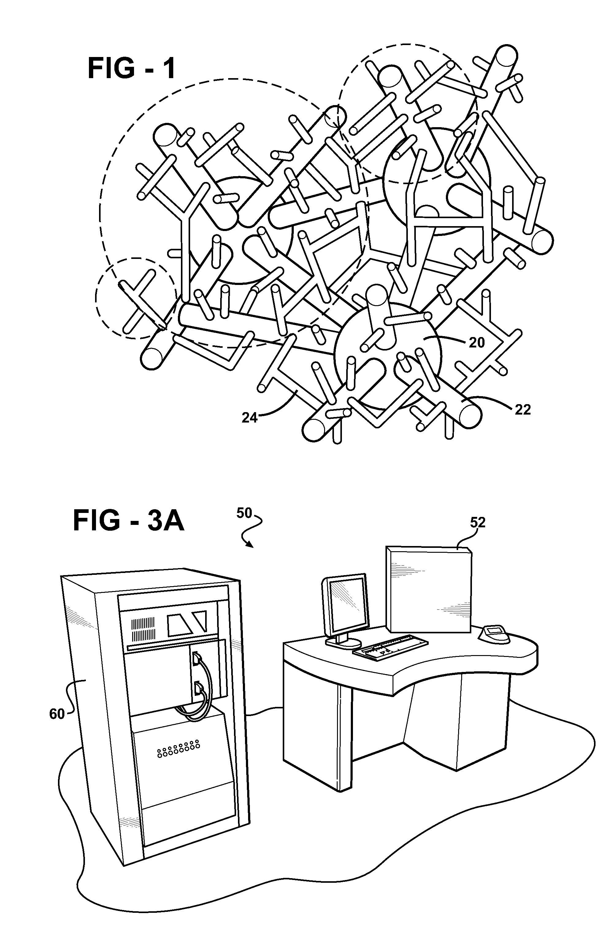
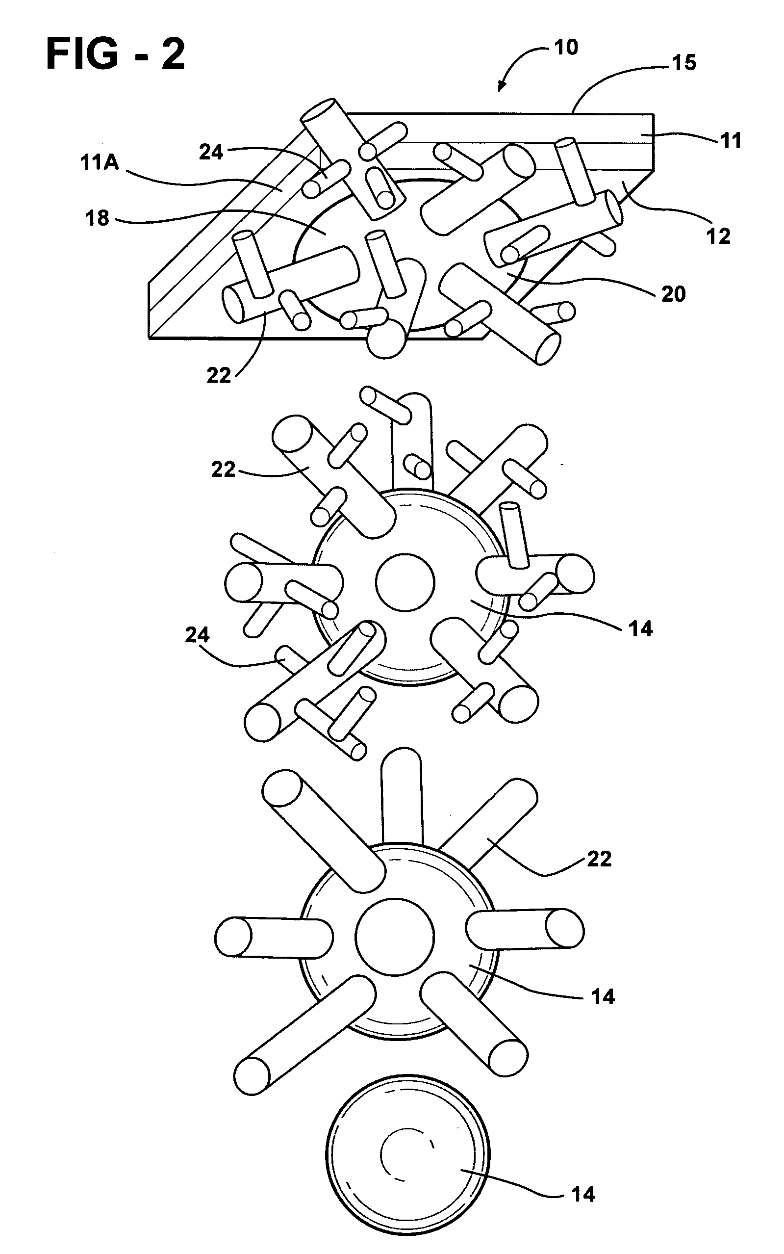
[0045] Referring to the Figures, wherein like numerals indicate like or corresponding parts, an electrode of the present invention is generally shown at 10. The electrode 10 of the present invention is formed from a metal tape, i.e. foil, generally indicated at 11 and shown fragmentally in FIGS. 1 and 2, is used to form a first electrode such as an anode and a second electrode such as cathode (both not shown), spaced by a separator and combined into a cell (not shown) for producing electric power without limiting the scope of the present invention. The metal current collector or substrate 11 of the first electrode and the second electrode has opposed sides 12 and 14, as best illustrated in a cross sectional view shown in FIGS. 1 and 2.

[0046] The electrodes are combined into at least one cell used for a battery (not shown) for an automotive vehicle (not shown). The present inventive concept has various other applications including and not limited to high efficiency thin-film photovo...


PUM


Abstract

An electrode and method of forming the same of the present invention is used for the high-rate deposition of materials, such as carbon, silicon, metals, metal oxides, and the like, onto a metal substrate defined by a metal tape used as cathode or anode combined with a separator to form a fuel cell of a secondary battery, metal-ceramic membranes, film composite metal-ceramaic materials for electronic devices. The method is cost effective and is directed to form the electrode with improved and high porosity.

Description

FIELD OF THE INVENTION [0001] This application claims priority to a provisional patent application Ser. No. 60 / 755,621 filed on Dec. 29, 2005 and incorporated herewith by reference in its entirety.FIELD OF THE INVENTION [0002] The subject invention relates to an apparatus and method for manufacturing an electrode for a cell having improved cell charged capacity, C-rate performance and recycling stability. BACKGROUND OF THE INVENTION [0003] The term “nanotechnology” generally refers to objects, systems, mechanisms and assemblies smaller than one ten of micron and larger than 1 nm. In recent years nanotechnology has been used to make products, that is, raw materials are processed and manipulated until the desired product is achieved. In contrast, nanotechnology mimics nature by building a product from the ground up using a basic building block—the atom. In nanotechnology atoms are arranged to create the material needed to create other products. Additionally, nanotechnology allows for ...

Claims


Application Information

Patent Timeline
IPC IPC(8): H01M4/02H01M4/62B05D5/12B05D1/02H01M4/13H01M4/1393H01M10/052H01M10/36
CPCH01M4/13H01M4/1393H01M4/624H01M4/625Y02E60/122H01M4/661H01M4/805H01M4/86H01M10/052H01M4/626Y02E60/10Y02E60/50
Inventor KALYNUSHKIN, YEVGENNOVAK, PETER
Owner NANOENER
Why Eureka
Try Eureka