

Signal-on architecture for electronic, oligonucleotide-based detectors
a technology of oligonucleotide and signal-on architecture, which is applied in the field of bioelectronic detectors based on oligonucleotides, can solve the problem of continuous attachment and achieve the effect of increasing the detectable signal
- Summary
- Abstract
- Description
- Claims
- Application Information
AI Technical Summary
Benefits of technology
Problems solved by technology
Method used
Image

Examples
example 1
A. Example 1
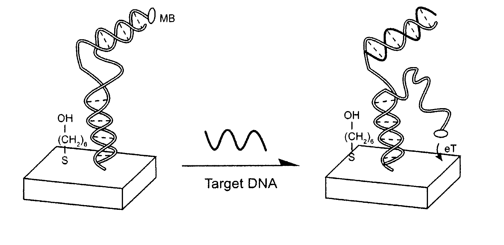
Reusable Reagentless Detector
[0065] Modified DNA oligonucleotides were synthesized by BioSource, Int. (Foster City, Calif.), purified via C18 HPLC and PAGE, and confirmed by mass spectroscopy. The sequences of these three oligonucleotides employed are given below:
SEQ ID NO. 1:5′-HS-(CH2)6GCGAGGTAAAACGACGGCCAGTCTCGC-(CH2)7-MB-3′SEQ ID NO. 2:5′-CCCTATGTATGCTCTTTGTTGTGGCGAGACTGGC-3′SEQ ID NO. 3:5′-GCCAGTCTCGCCACAACAAAGAGCATACATAGGG-3′
[0066] The detector was fabricated using polycrystalline gold disk electrodes (1.6 mm diameter, BAS, West Lafayette, Ind.). The electrodes were prepared by polishing with diamond and alumina (BAS), sonicating in water, and electrochemically cleaning (a series of oxidation and reduction cycling in 0.5 M NaOH; 0.5 M H2SO4; 0.01 M KCl / 0.1 M H2SO4; and 0.05 M H2SO4) before being modified with the thiolated probe DNA. To fabricate the detectors a clean gold surface was reacted with a solution of thiolated blocker DNA (SEQ ID NO: 1), 0.5 μM inclu...
example 2
B. Example 2
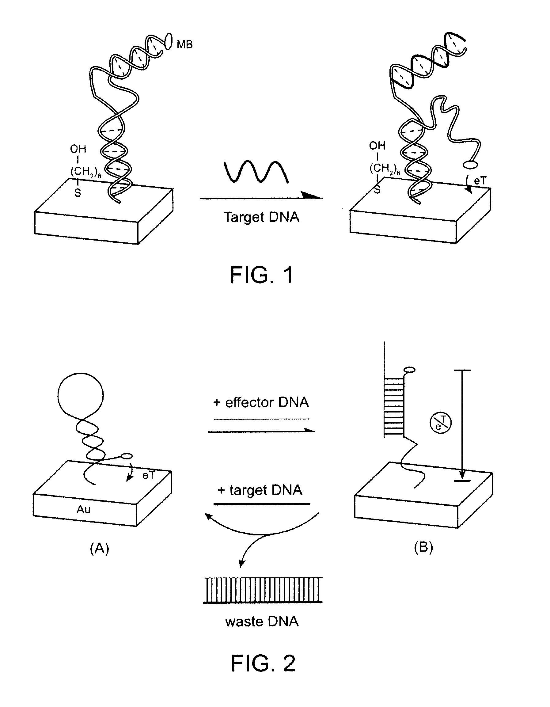
Dual Complementarity Region Detector
[0069] Modified DNA oligonucleotides were synthesized by BioSource, Int. (Foster City, Calif.), purified via C18 HPLC and PAGE, and confirmed by mass spectroscopy. The sequences of these three oligonucleotides employed are given below:
SEQ ID NO. 4:5′-HS-(CH2)6-GCGAGTTAGACCGATCCCCCCCCTTCGTCCAGTCTTTT-3′SEQ ID NO. 5:5′-MB-(CH2)6-GACTGGACGCCCCCCCATCGGTCTAACTCGC-3′SEQ ID NO. 6:5′-AAAAGACTGGACGAA-3′
[0070] The detector was fabricated using polycrystalline gold disk electrodes (1.6 mm diameter, BAS, West Lafayette, Ind.). The electrodes were prepared by polishing with diamond and alumina (BAS), sonicating in water, and electrochemically cleaning (a series of oxidation and reduction cycling in 0.5 M NaOH; 0.5 M H2SO4; 0.01 M KCl / 0.1 M H2SO4; and 0.05 M H2SO4) before being modified with the thiolated sensor DNA. To fabricate the detectors a clean gold surface was reacted with a solution of thiolated sensor DNA (SEQ ID NO. 4), 0.5 μM includin...
example 3
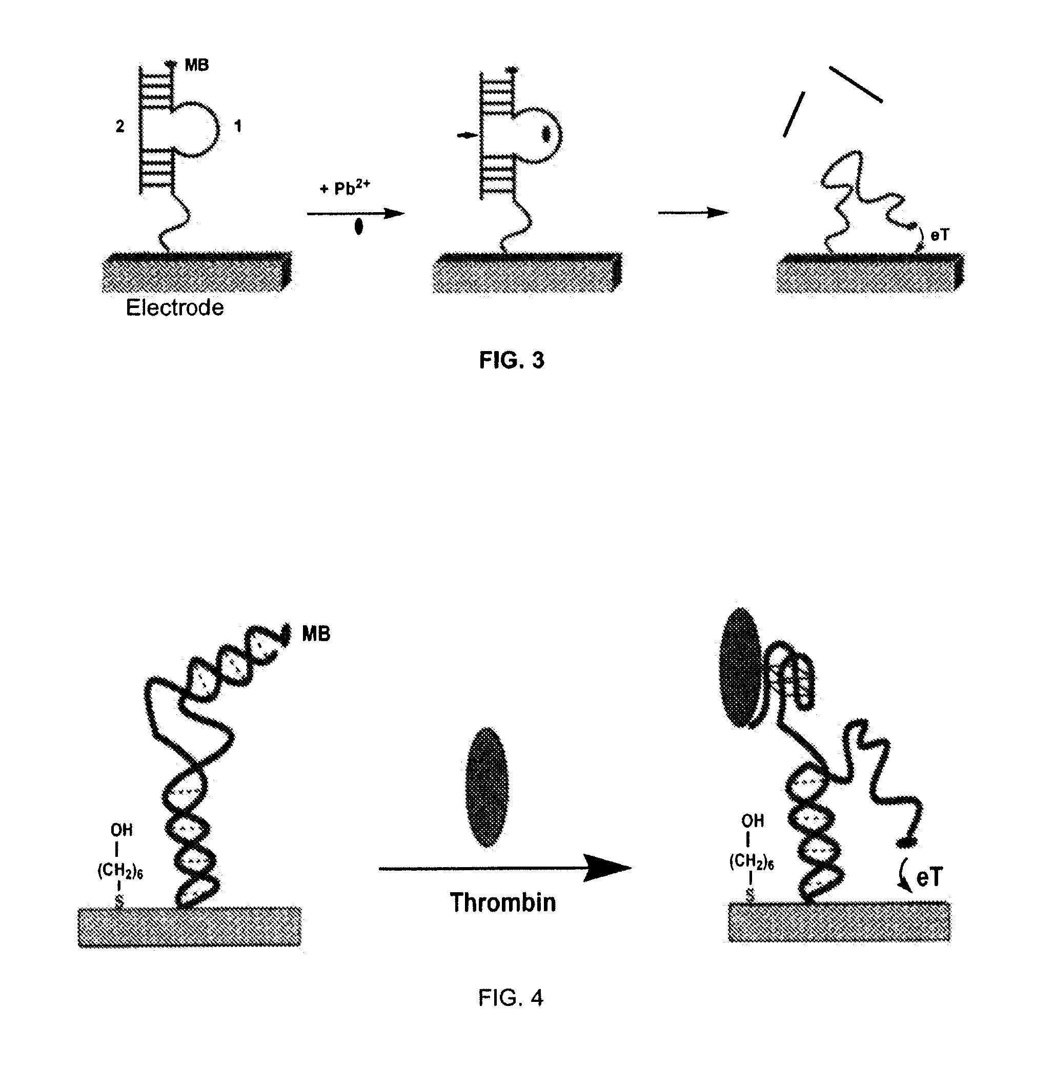
C. Example 3
[0073] Labeled DNA oligonucleotides were synthesized by BioSource, Int. (Foster City, Calif.), and purified via C18 HPLC and PAGE, and confirmed by mass spectroscopy. The sequences of these three oligonucleotides employed are given below:
SEQ ID NO. 7:5′-HS-(CH2)6-CCATCTCCACTTGGTTGGTGTGGTTGG-3′SEQ ID NO. 8:5′-MB-(CH2)2-CCAACTTTTAAGTGGAGATGG-3′SEQ ID NO. 9:5′-HS-(CH2)6-CCATCTCCACTTGGTGGTGGTTGTGGT-3′SEQ ID NO. 10:5′-MB-(CH2)2-ACCACTTTTAAGTGGAGATGG-3′
[0074] The detector was fabricated using polycrystalline gold disk electrodes (1.6 mm diameter, BAS, West Lafayette, Ind.). The electrodes were prepared by polishing with diamond and alumina (BAS), sonicating in water, and electrochemically cleaning (a series of oxidation and reduction cycling in 0.5 M NaOH; 0.5 M H2SO4; 0.01 M KCl / 0.1 M H2SO4; and 0.05 M H2SO4) before being modified with the thiolated DNA. The clean gold surface was interacted with a solution of thiolated thrombin aptamer sensor (SEQ I...
PUM
| Property | Measurement | Unit |
|---|---|---|
| Metallic bond | aaaaa | aaaaa |
| Biological properties | aaaaa | aaaaa |
Abstract
Description
Claims
Application Information