Critical velocity reduction in a gas well

Active Publication Date: 2007-07-12
WEATHERFORD TECH HLDG LLC
View PDF6 Cites 7 Cited by
  • Summary
  • Abstract
  • Description
  • Claims
  • Application Information

AI Technical Summary

Benefits of technology

[0006] The presently disclosed apparatus provides a dead string for reducing the critical velocity of gas produced in a perforated interval of a gas well while still providing the well operator with the ability to access the well bore below the dead string. The apparatus features a tubing string extending into the gas well and having a ported member co-axially disposed within the tubing string. Typical ported members include sliding sleeve valves or ported flow subs, which are described in more detail below. The ported member will typically be

Problems solved by technology

As natural gas and associated liquids are extracted during production, a gradual loss of reservoir pressure occurs in some natural gas wells, thus decreasing the pressure differential.
Several actions that well operators would typically perform to diagnose and correct these sand problems are not possible with the apparatus illustrated in FIG. 2. and other dead string installations or designs known in the art.
Thus the operator lacks the ability to run a wireline to the bottom of the wellbore to check for sand fill levels below the dead string 14.
This operation is not possible with the configuration illustrated in FIG. 2 because the holes in

Method used


Image

  • Critical velocity reduction in a gas well
  • Critical velocity reduction in a gas well
  • Critical velocity reduction in a gas well

Examples


Embodiment Construction

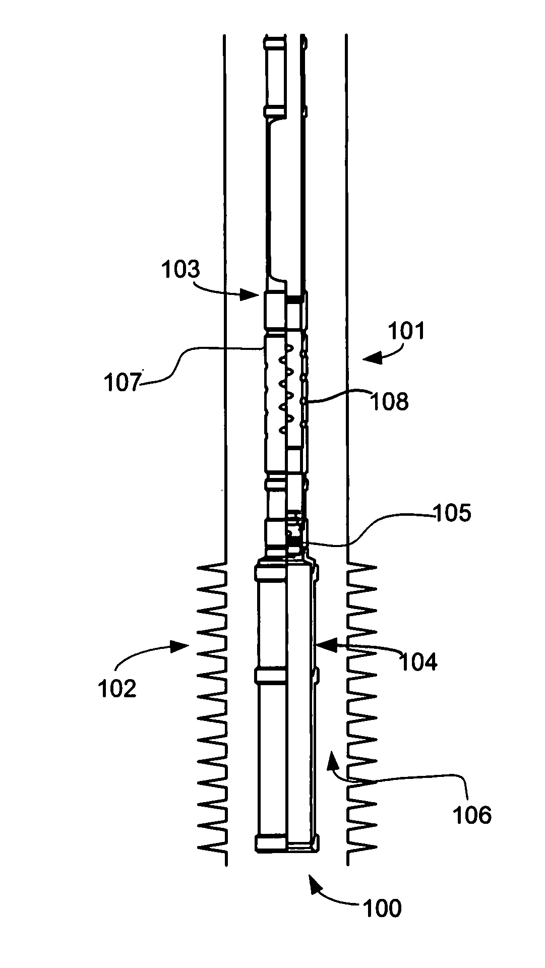
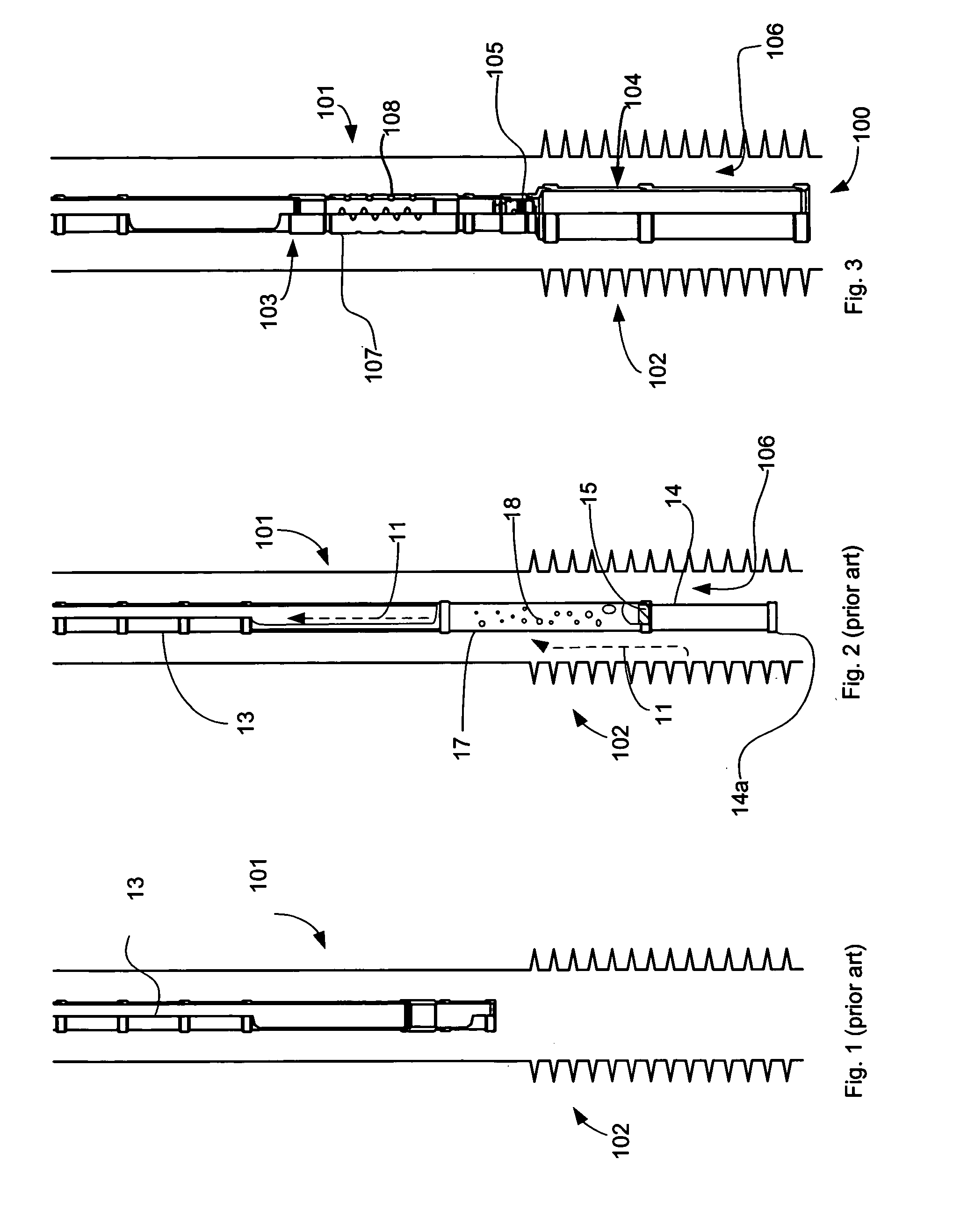
[0015]FIG. 3 illustrates an embodiment of the presently disclosed apparatus. The apparatus 100 can be deployed in a cased wellbore 101 having a perforated interval 102. Apparatus 100 includes a production tubing section 103 and a dead string 104. The inner diameter (ID) of production tubing section 103 and the ID of dead string 104 are isolated from each other by retrievable plug 105. During operation, gas and formation fluids in perforated interval 102 flow in the annular region 106 around dead string 104. Dead string 104 typically has a larger outer diameter (OD) than production tubing section 103 but could be the same size as the production tubing. For example, in a well with 4½″ casing having an ID of 4″, the production string might have an OD of 2⅜″ and the dead string might have an OD of 2⅞″. Dead string 104 reduces the flow area in the perforated interval, thereby decreasing the critical velocity needed to lift produced liquids in the wellbore reducing the effects of liquid l...


PUM


Abstract

Disclosed herein is a system for enhancing the recovery of gas in a perforated interval of a gas well. The system features a tubing string having a dead string attached for reducing the flow area of the annulus in the perforated interval, thereby reducing the critical velocity of the gas, i.e., the velocity required to overcome backpressure due to fluids in the well column. The system includes a ported member for receiving gas from the annulus into the tubing string. The ported member and the dead string are isolated from each other by a retrievable plug. The disclosed system provides access from the surface through the dead string for diagnostic or corrective operations. The system also provides delivery of reagents such as foamers to the perforated region to further reduce the critical velocity.

Description

FIELD OF THE INVENTION [0001] The invention relates to the recovery of natural gas from natural gas wells and more particularly concerns an apparatus for reducing the critical velocity required to unload extended perforated intervals in liquid-loaded gas wells. BACKGROUND OF THE INVENTION [0002]FIG. 1 illustrates a production tubing string 13 deployed in a cased natural gas wellbore 101 having an extended perforated interval 102. The production rate of a natural gas well is a function of the pressure differential between the underground reservoir and the well head. This differential is decreased by back pressure against the reservoir pressure. As natural gas and associated liquids are extracted during production, a gradual loss of reservoir pressure occurs in some natural gas wells, thus decreasing the pressure differential. Natural gas wells produce liquids such as water and hydrocarbon. Removal of these produced liquids depends on the velocity of the gas stream produced from the f...

Claims


Application Information

Patent Timeline
IPC IPC(8): E21B43/00
CPCE21B43/12
Inventor CAMPBELL, THOMAS SCOTT
Owner WEATHERFORD TECH HLDG LLC
Why Eureka
Try Eureka