Optical component for optical communication
a technology of optical communication and optical components, applied in the field of optical components for optical communication, can solve the problems of substantially impossible to achieve in view of cost and manufacture procedure, extremely steep refractive index gradient, and difficult to form such curved surfaces, etc., and achieves the effect of easy automation, simple centering, and increased degree of freedom of lens design
- Summary
- Abstract
- Description
- Claims
- Application Information
AI Technical Summary
Benefits of technology
Problems solved by technology
Method used
Image
Examples
example 1
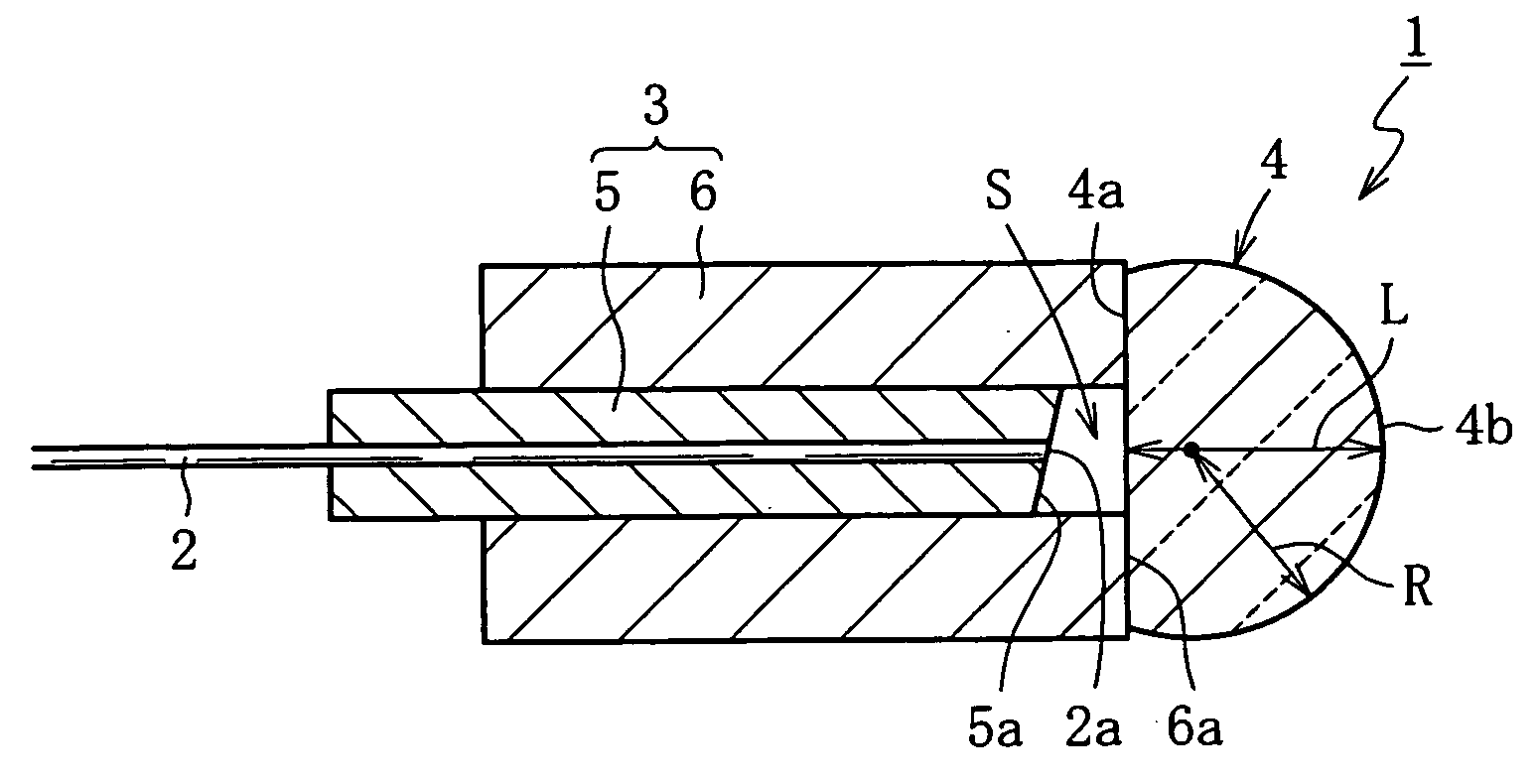
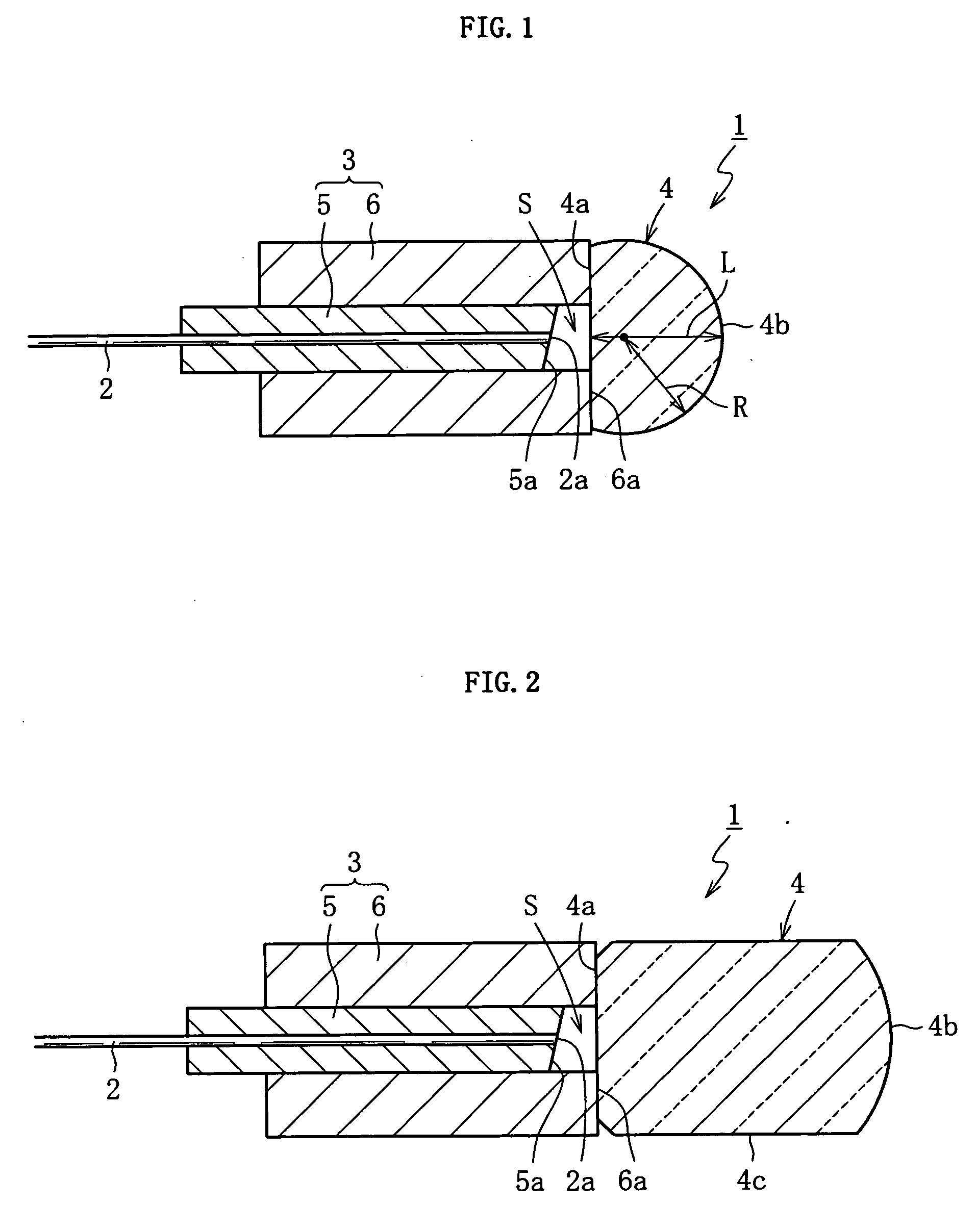
[0058]In Example 1 of the present invention, the optical collimator 1 having the structure shown in FIG. 1 (first embodiment) was produced. In the optical collimator 1 according to Example 1, the first holding member 5 was made of glass and had an outer diameter of 0.25 mm, an inner diameter of 0.126 mm, and the entire length of 3 mm. The end surface of the first holding member 5 was polished such that the end surface was tilted at a tilt angle of 8 degrees relative to the normal to the optical axis, thereby forming the oblique surface 5a. The optical fiber 2 whose end surface was polished together with the end surface of the first holding member 5 (before the formation of the oblique surface 5a) was held in the inner hole of the first holding member 5. The second holding member 6 of the optical collimator 1 was made of glass and had an outer diameter of 1 mm, an inner diameter of 0.255 mm, and the entire length of 2 mm. The second holding member 6 was fitted to the outer circumfere...
example 2
[0061]In Example 2 of the present invention, the optical collimator 1 having the structure shown in FIG. 2 (second embodiment) was produced. In the optical collimator 1 according to Example 2, for example, a size and a material of each portion in each of the first holding member 5 and the second holding member 6 were identical to those in Example 1 described above. The lens 4 of the optical collimator 1 was formed by using, as an original lens, a spherical lens which had a diameter of 2 mm and was made of optical glass RH-21 (which is produced by Nippon Electric Glass Co., Ltd.) whose refractive index was substantially uniform. Apart of the spherical lens was subjected to polishing processing or the like such that a distance between the flat portion 4a and the end vertex of the spherical portion 4b became 1.8 mm. The bonding state between the second holding member 6 and the lens 4 and the fact that the antireflective coating was formed in place are identical to those in Example 1 de...
example 3
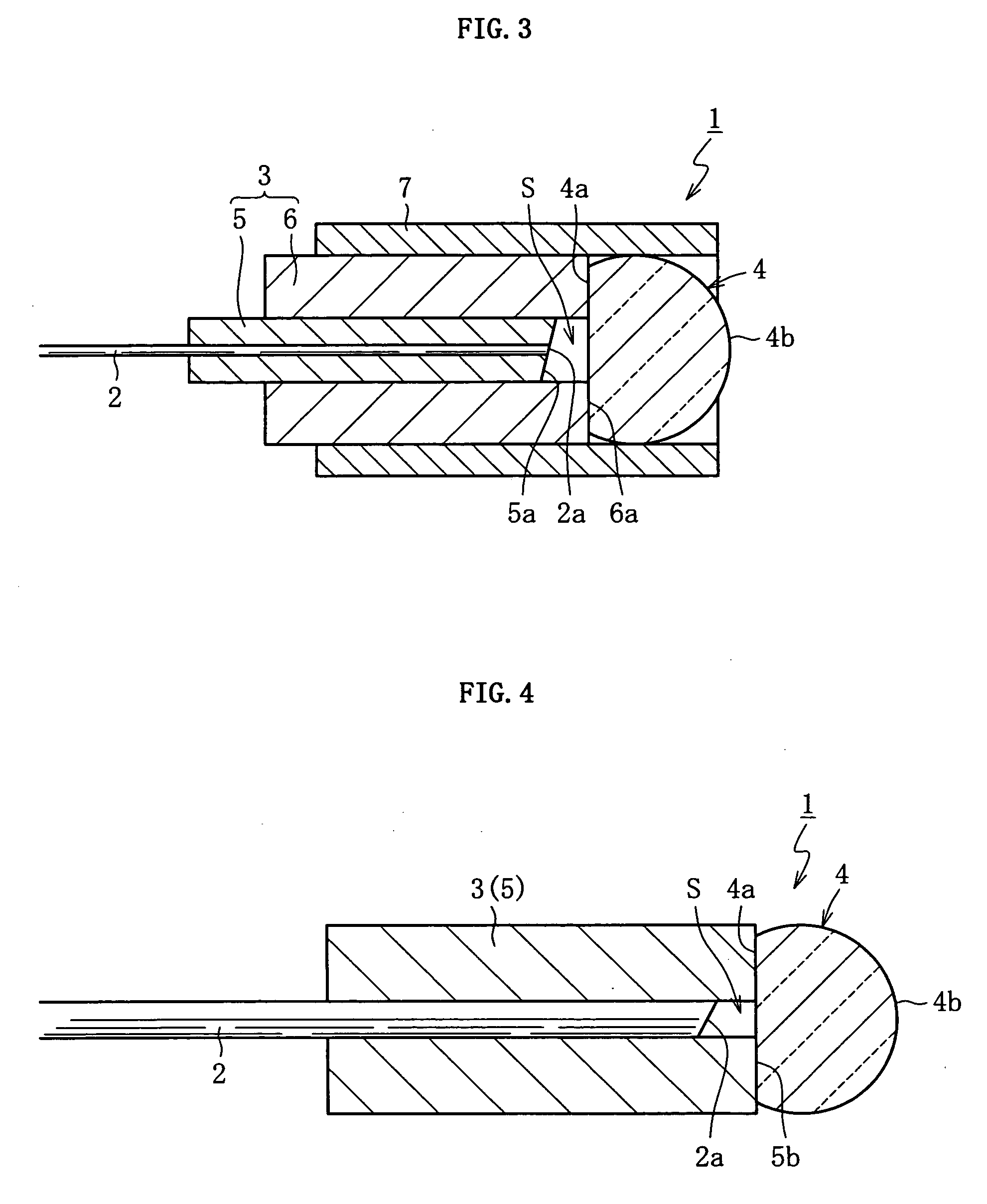
[0064]In Example 3 of the present invention, the optical collimator 1 having the structure shown in FIG. 3 (third embodiment) was produced. In the optical collimator 1 according to Example 3, for example, a size and a material of each portion in each of the first holding member 5 and the second holding member 6 were identical to those in Example 1 or 2 described above. The lens 4 of the optical collimator 1 was formed by using, as an original lens, a spherical lens which had a diameter of 1 mm and was made of optical glass RH-21 (which is produced by Nippon Electric Glass Co., Ltd.) whose refractive index was substantially uniform. A part of the spherical lens was subjected to polishing processing or the like such that a distance between the flat portion 4a and the end vertex of the spherical portion 4b became 0.7 mm. The coating tube 7 of the optical collimator 1 was made of glass and had an outer diameter of 1.4 mm, an inner diameter of 1 mm, and the entire length of 3 mm. While t...
PUM
| Property | Measurement | Unit |
|---|---|---|
| diameter | aaaaa | aaaaa |
| refractive index | aaaaa | aaaaa |
| beam diameter | aaaaa | aaaaa |
Abstract
Description
Claims
Application Information
 - R&D
- Intellectual Property
- Life Sciences
- Materials
- Tech Scout
- Unparalleled Data Quality
- Higher Quality Content
- 60% Fewer Hallucinations
Browse by: Latest US Patents, China's latest patents, Technical Efficacy Thesaurus, Application Domain, Technology Topic, Popular Technical Reports.
© 2025 PatSnap. All rights reserved.Legal|Privacy policy|Modern Slavery Act Transparency Statement|Sitemap|About US| Contact US: help@patsnap.com


