Surface coated cutting tool

a cutting tool and surface coating technology, applied in the field of surface coating cutting tools, can solve the problems of film peeling, notch wear, lowering wear resistance, etc., and achieve the effect of stable and good finished surfaces

Active Publication Date: 2007-07-19
KYOCERA CORP
View PDF20 Cites 19 Cited by
  • Summary
  • Abstract
  • Description
  • Claims
  • Application Information

AI Technical Summary

Benefits of technology

[0015] The present invention provides a excellent surface coated cutting tool which can suppress influence of heat generating in wet high speed cutting processes on a cutting edge and show excellent resistance to wear and fracture even in high speed cutting.
[0016] The present invention also provides a surface coated cutting tool which can suppress adhesion of a work material to a flank face easily caused by high speed cutting processes and have longer life and highly accurate finished surface.
[0017] The present inventors have found a new fact that improved wettability to a cutting fluid on the rake face of a surface coated cutting tool makes it possible to spread a cutting fluid throughout the surface of a cutting tool, thereby sufficiently showing the cooling effect of a cutting fluid and reducing temperature rise of a cutting edge caused by cutting. As a result, it is possible to obtain a excellent surface coated cutting tool which can prevent a hard layer from deteriorating due to temperature rise of a cutting edge by cutting and show excellent resistance to wear and fracture even in high speed cutting processes.

Problems solved by technology

Consequently, a conventional tool is tend to cause lowering wear resistance, film peeling, notch wear, poor accuracy in operations due to plastic deformation of a cutting edge and increased cutting resistance.
These cause sudden tool damage such as fracture of a cutting edge and occurrence of abnormal wear, making it difficult for a cutting tool to have a longer life.
In particular, there have been such problems as the high-temperature state of a rake face and a cutting edge, progress of crater wear due to deterioration of a hard layer and film peeling.
When a work material adheres to a flank face of a tool, there are problems such as poor operation accuracy and deteriorated surface roughness of a work material.
In addition, when the adhering material is removed, damage to a cutting edge such as peeling of a hard layer and chipping is tend to occur.
In particular, at the time of high-speed cutting processes for finished surface, adhesion of a work material to a flank face has been a large problem.
However, a smoothed surface obtained by processing the surface including a cutting edge of a hard layer as mentioned in these publications reduces cutting resistance and improves tribology property, but does not sufficiently spread a cutting fluid throughout the surface of a tool.
In particular, a cutting fluid cannot sufficiently spread through a rake face which reaches very high temperature during cutting.
This makes it impossible to sufficiently attain cooling effect by a cutting fluid and makes it difficult to quickly release the heat generated by cutting.
There has been also the problem that even in wet cutting where heat is relatively hardly generated, in case of high-speed cutting processes, suddenly decreased wear resistance shortens a tool life.
Moreover, on a flank face which has large influence on accuracy of the finished surface of a work material, a smoothed surface obtained by processing the surface including a cutting edge of a hard layer is not enough alone.
Namely, cutting resistance is reduced and tribology property is improved, but in case of high speed cutting, adhesion of a work material to a flank face cannot be inhibited, resulting in separation of an adhering work material, film peeling accompanying this and tool damage such as chipping of a cutting edge.

Method used


Image

  • Surface coated cutting tool
  • Surface coated cutting tool
  • Surface coated cutting tool

Examples


first embodiment

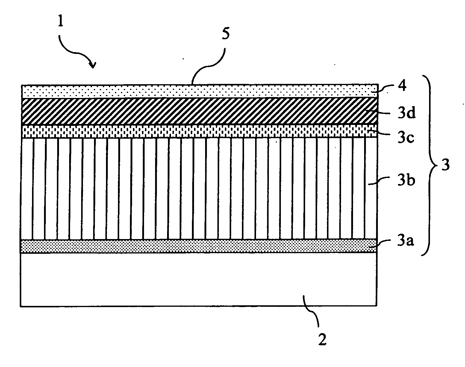
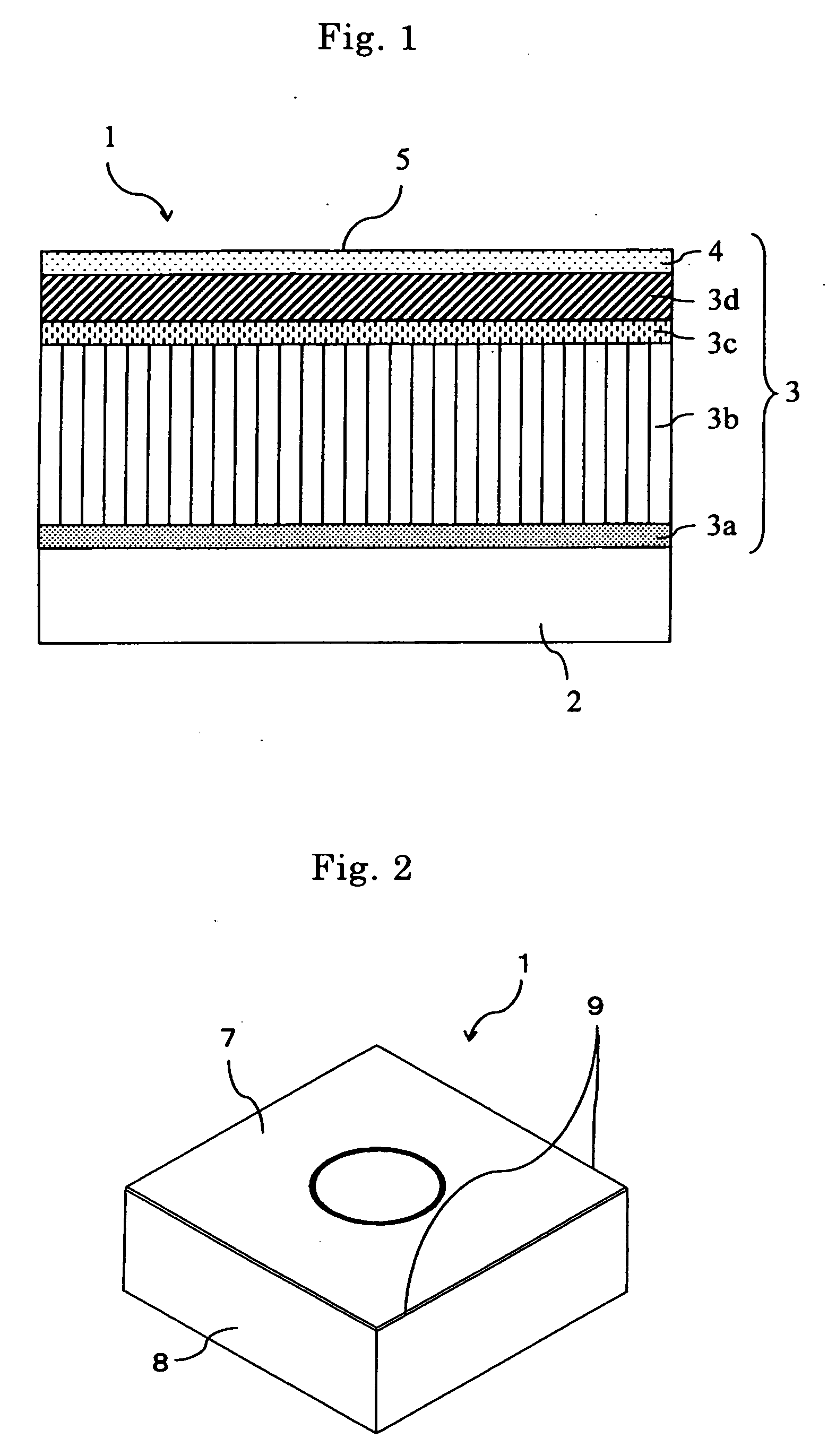
[0032]FIG. 1 is a schematic cross-sectional view of enlarged main part, showing layer structure of a hard layer according to the first embodiment. FIG. 2 is a schematic perspective view showing a surface coated cutting tool according to this embodiment. FIG. 3 is a pattern diagram to describe a method of measuring a contact angle of water θ on the rake face.

[0033] The surface coated cutting tool of this embodiment is a throw-away tip type cutting tool (hereinafter, referred to simply as tool in some cases). As shown in FIGS. 1 and 2, a tool 1 comprises an approximately flat-plate-like substrate 2 and a hard layer 3 formed on the surface of the substrate 2. Furthermore, as shown in FIG. 2, the tool 1 has a structure where a rake face 7 is provided on the principal surface of the substrate 2, a flank face 8 is provided on the side surface and a cutting edge 9 is provided on the cross-ridge portion of the rake face 7 and the flank face 8.

[0034] As the substrate 2, for example, cement...

second embodiment

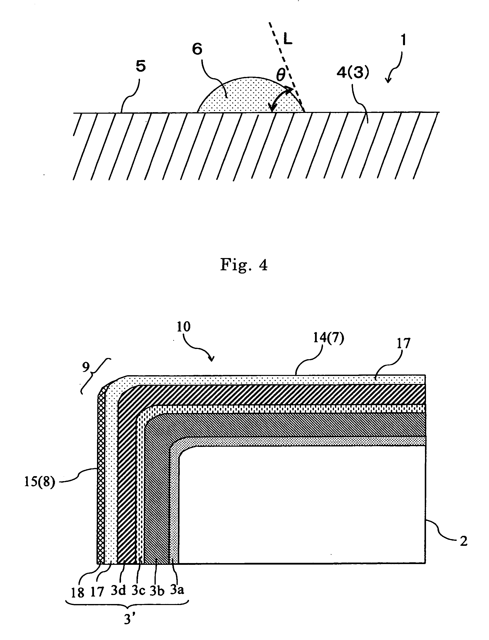
[0063]FIG. 4 is a schematic cross-sectional view of enlarged main part, showing layer structure of a hard coated layer according to the second embodiment. FIG. 5(a) is a pattern diagram to describe a method of measuring a contact angle of water θR on the rake face, and FIG. 5(b) is a pattern diagram to describe a method of measuring a contact angle of water oF on the flank face. FIG. 6 is a schematic cross-sectional view of enlarged main part, showing layer structure of another hard coated layer according to the second embodiment. In FIGS. 4 to 6, the same numerical references are given to the parts identical or equivalent to the above-mentioned structure of FIGS. 1 to 3 to omit description.

[0064] The cutting tool according to this embodiment is different from the above embodiment in that the contact angle of water of the hard coated layer has predetermined relationship on the rake face and the flank face. Specifically, as shown in FIG. 4, a hard coated layer 3′ of this embodiment ...

example i

[0112] First, to tungsten carbide (WC) powder having a mean particle size of 1.5 μm, 6% by weight of metallic cobalt (Co) powder having a mean particle size of 1.2 μm, 0.5% by weight of titanium carbide (TiC) powder having a mean particle size of 2.0 μm and 5% by weight of TaC powder having a mean particle size of 2.0 μm were added, mixed. Next, this mixture was molded into a cutting tool shape (CNMG120412) by press molding, followed by debinding process, and then sintered in a vacuum of 0.01 Pa at 1500° C. for one hour. Thereby, cemented carbide was prepared. In addition, through brushing, the cemented carbide so prepared underwent edge treatment (honing R) from the rake face.

[0113] Next, through chemical vapor deposition (CVD) method, various hard layers composed of a multilayer of layers having the composition shown in Table 2 were formed on the above cemented carbide. The deposition conditions of each layer in Table 2 were presented in Table 1. At this time, the reacting furnac...


PUM

PropertyMeasurementUnit
contact angleaaaaaaaaaa
mean particle sizeaaaaaaaaaa
surface roughnessaaaaaaaaaa

Abstract

A surface coated cutting tool comprises a substrate and a hard layer formed on the surface of the substrate, and a contact angle of water θ on the rake face of the hard layer is in the range of 30 to 80°. A surface coated cutting tool comprises a substrate and a hard layer formed on the surface of the substrate, and a contact angle of water θR on the rake face of the hard layer and a contact angle of water θF on the flank face of the hard layer have a relation of θR<θF. Thereby, excellent resistance to wear and fracture can be shown, leading to a excellent surface coated cutting tool.

Description

[0001] Priority is claimed to Japanese Patent Application No. 2005-202702 filed on Jul. 12, 2005, No. 2005-342879 filed on Nov. 28, 2005, the disclosure of which is incorporated by reference in its entirety. BACKGROUND OF THE INVENTION [0002] 1. Field of the Invention [0003] The present invention relates to a surface coated cutting tool comprising a hard layer formed on the surface and having cutting characteristics such as resistance to fracture and wear. [0004] 2. Description of Related Art [0005] Conventionally, a surface coated cutting tool having a hard layer formed on the surface of a substrate has been widely used. In many cases, a tool wherein a hard layer composed of a single layer or a multilayer of layers such as TiC layer, TiN layer, TiCN layer, Al2O3 layer and TiAlN layer is formed on the surface of a hard substrate such as cemented carbide, cermet and ceramics has been used as the cutting tool. [0006] Cutting processes are carried out with such a cutting-tool largely i...

Claims


Application Information

Patent Timeline
Patent Type & Authority Applications(United States)
IPC IPC(8): B32B9/00
CPCB23B27/141B23B2224/04B23B2224/36B23B2228/04B23B2228/08B23B2228/10Y10T428/25C23C16/34C23C16/36C23C16/403C23C30/005Y10T407/27Y10T428/30B23B2250/12
Inventor TANIBUCHI, TAKAHITOITOH, HIROTOSHI
Owner KYOCERA CORP
Why Eureka
Try Eureka