Fuel cell cathode manufacturing method and fuel cell manufacturing method

a fuel cell and manufacturing method technology, applied in the manufacture of final products, cell components, electrochemical generators, etc., can solve the problems of high cost of platinum, great obstacle to cost cutting and mass production, etc., and achieve the effect of improving current density and energy density

Active Publication Date: 2007-07-19
TDK CORPARATION
View PDF2 Cites 5 Cited by
  • Summary
  • Abstract
  • Description
  • Claims
  • Application Information

AI Technical Summary

Benefits of technology

[0024] The present invention can provide a method of manufacturing a cathode for a fuel cell which can im

Problems solved by technology

However, platinum is expensive and thus is a great obstacle to

Method used


Image

  • Fuel cell cathode manufacturing method and fuel cell manufacturing method
  • Fuel cell cathode manufacturing method and fuel cell manufacturing method
  • Fuel cell cathode manufacturing method and fuel cell manufacturing method

Examples


example 1

[0080] As a metal complex, 5,10,15,20-tetraphenylporphyrinatocobalt(II) (manufactured by Aldrich) was deposited by vacuum deposition onto a disk electrode having a diameter of 6 mm made of glassy carbon, so as to form a precursor layer made of a metal complex. Here, from the change in weight between before and after the deposition, it was proved that the amount of coating of the metal complex was 20 μg / cm2.

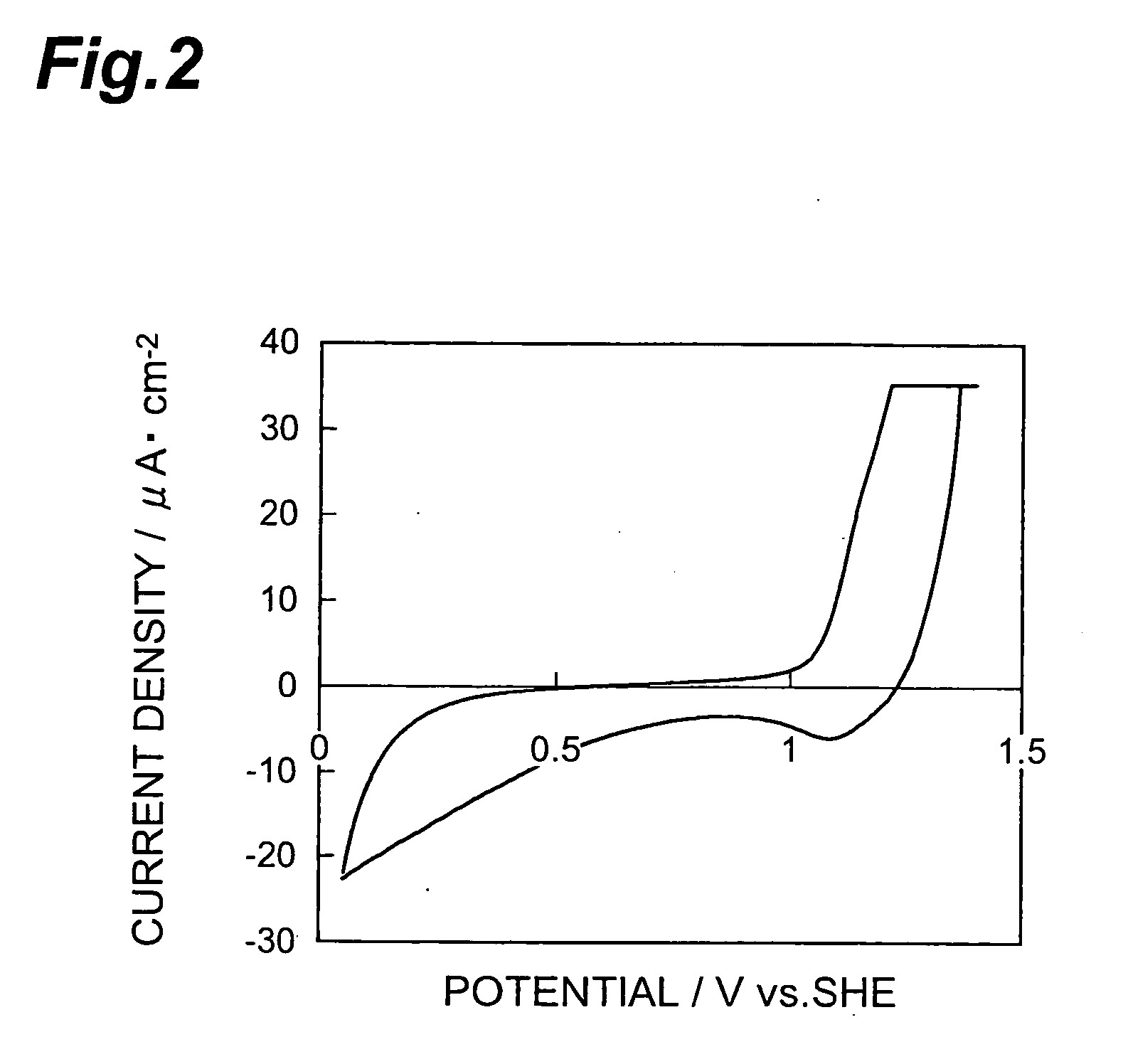
[0081] Next, using thus obtained multilayer body in which the precursor layer was formed on the disk electrode as a working electrode, platinum as a counter electrode, a standard hydrogen electrode (SHE) as a reference electrode, and an oxygen-saturated 0.5-M aqueous sulfuric acid solution as an electrolyte, the multilayer body was provided with a potential by 50 cycles of potential sweeping at 100 mV / s within the range of 1.4 V to 0.05 V. This formed a catalyst layer, thereby completing the making of the electrode. FIG. 2 shows the relationship between potential and current dens...

example 2

[0082] The electrode of Example 2 was made as in Example 1 except that potential sweeping for the multilayer body was carried out within the range of 1.6 V to 0.05 V. FIG. 3 shows the relationship between potential and current density in the 50th cycle of potential sweeping in Example 2.

example 3

[0083] As a metal complex, 20 mg of 5,10,15,20-tetraphenylporphyrinatocobalt(II) (manufactured by Aldrich) were dissolved in 10 ml of N-methylpyrrolidone, so as to prepare a coating liquid. This coating liquid was applied dropwise onto a disk electrode having a diameter of 6 mm made of glassy carbon, so as to form a uniform coating, which was then dried, so as to form a precursor layer made of a metal complex. Here, from the change in weight between before and after forming the precursor layer, it was proved that the amount of coating of the metal complex was 20 μg / cm2.

[0084] Next, using thus obtained multilayer body in which the precursor layer was formed on the disk electrode as a working electrode, platinum as a counter electrode, a standard hydrogen electrode (SHE) as a reference electrode, and an oxygen-saturated 0.5-M aqueous sulfuric acid solution as an electrolyte, the multilayer body was provided with a potential by 50 cycles of potential sweeping at 100 mV / s within the ra...


PUM

PropertyMeasurementUnit
Electric potential / voltageaaaaaaaaaa
Lengthaaaaaaaaaa

Abstract

The method of manufacturing a cathode for a fuel cell in accordance with the present invention is a method of manufacturing a cathode for a fuel cell equipped with a catalyst layer containing a catalyst, and includes a potential providing step of providing a precursor layer containing the catalyst with a potential higher than 1.3 V with reference to a standard hydrogen electrode, so as to form the catalyst layer.

Description

TECHNICAL FIELD [0001] The present invention relates to a method of manufacturing a cathode for a fuel cell and a method of manufacturing a fuel cell. BACKGROUND ART [0002] Attention has recently been focused on fuel cells as an energy supply source which has a high power generation efficiency and theoretically yields only water as a reaction product, while being excellent in environmental friendliness. Depending on species of electrolytes employed, such fuel cells are roughly classified into low-temperature operating fuel cells such as those of alkali, solid polymer, and phosphate types, and high-temperature operating fuel cells such as those of molten carbonate and solid oxide types. Among them, polymer electrolyte fuel cells (PEFCs) using a solid polymer s their electrolyte, which can attain a high density / high output in a compact structure while being operable in a simple system, have been widely studied not only as a stationary distributed power supply but also as a power suppl...

Claims


Application Information

Patent Timeline
IPC IPC(8): H01M4/88
CPCH01M4/8853H01M4/90H01M4/9008H01M8/1011Y10T29/49108H01M2008/1095Y02E60/523Y02E60/50H01M2004/8689Y02P70/50
Inventor SANO, ATSUSHIMARUYAMA, SATOSHI
Owner TDK CORPARATION
Why Eureka
Try Eureka