Optical device for fluorescence imaging

an optical device and fluorescence imaging technology, applied in the field of optical devices for fluorescence imaging, can solve the problems of difficult bonding of components, inability to consider the contribution of the adhesive to be employed for the bonding between the lens and the lens, and deteriorating the contrast of the image of observation, so as to achieve high contrast, reduce noise generation, and reduce the effect of nois

Inactive Publication Date: 2007-07-19
OLYMPUS CORP
View PDF12 Cites 4 Cited by
  • Summary
  • Abstract
  • Description
  • Claims
  • Application Information

AI Technical Summary

Benefits of technology

[0026] The optical device for fluorescence imaging according to the present invention includes an endoscope for fluorescence imaging and a microscope for fluorescence imaging. Since a silicone-based bonding agent containing a low-autofluorescent substance is employed in the bonding of the optical elements in these optical devices for fluorescence imaging, the generation of autofluorescence as well as the generation of noise can be minimized, thereby enabling to observe fluorescence of high contrast through this optical device.
[0027] As described above in detail, since the optical device for fluorescence imaging according to one aspect of the present invention is featured in that the silicone-based bonding agent to be employed for bonding the optical elements contains a low-autofluorescent substance, the generation of autofluorescence as the bonding agent is irradiated can be minimized and the transmittance of the fluorescence of short wavelength region into the silicone-based bonding agent is also high without generating discoloration. Therefore, according to the optical device such as a microscope for fluorescence imaging or an endoscope for fluorescence imaging, which is constructed as described above, it is possible to observe an image of high contrast.

Problems solved by technology

Further, in the case of fluorescence imaging, since the autofluorescence of the optical materials constituting the optical system of the imaging device is fairly large, noise is generated due to this autofluorescence of the optical materials on the occasion of irradiating an excitation light, thereby considerably deteriorating the contrast of the image of observation.
However, the contribution of the adhesive to be employed for the bonding between lens and lens cannot be disregarded, thus necessitating further improvement in this respect.
Further, the objective lens disclosed in JA-A 11-23976 is accompanied with problems that even though it is constructed without using an adhesive, it is very difficult to bond the components each having a specific curvature to each other without using an adhesive, and that the bonded structure of lens each having different configuration is more likely to generate an optical strain due to change in temperature.
Even in the case of the fluorescence endoscope described in JA-A 2002-10969, even though it is possible to eliminate the reflected excitation light by means of the excitation light cut-off filter, it is impossible to eliminate the autofluorescence to be generated from the materials constituting the optical system, thus failing to overcome the problem of the deterioration of contrast.

Method used


Image

  • Optical device for fluorescence imaging
  • Optical device for fluorescence imaging
  • Optical device for fluorescence imaging

Examples


example 1

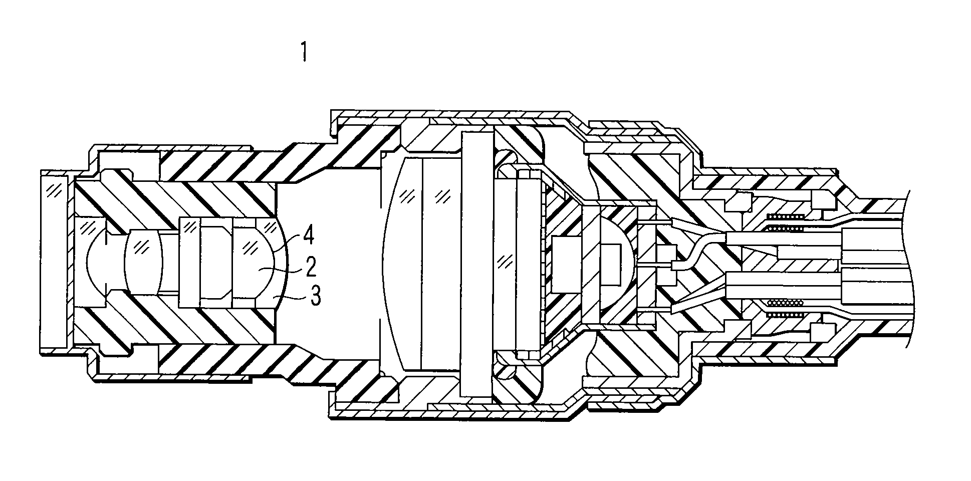
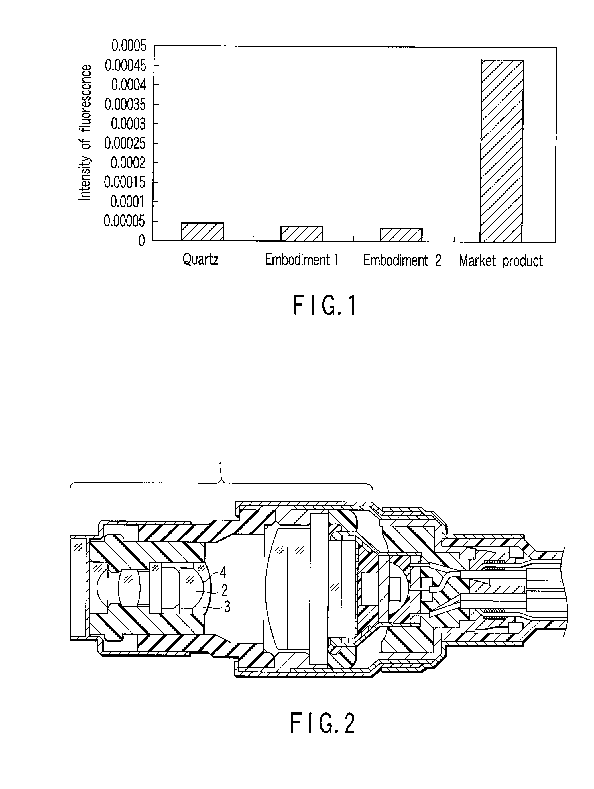
[0045]FIG. 2 is a cross-sectional view showing a distal end of the insert portion of the endoscope according to Example 1 of the present invention. The distal end of the insert portion of the endoscope shown in FIG. 2 is constructed such that an objective optical system for observation 1 equipped with a plurality of lenses is built into the distal main body. This objective optical system was constructed to include a bonded lens comprising a lens 2 and a lens 3 which were bonded to each other by the bonding agent (silicone adhesive) 4 of the aforementioned embodiment 1.

[0046] More specifically, a small quantity of the silicone adhesive 4 was coated on the bonding surface of the lens 3 and then the lens 2 was superimposed onto the lens 3 and the silicone adhesive 4 was allowed to spread all over the joint surface. The resultant body was left to stand at room temperature or heated to cure the silicone adhesive 4, thereby manufacturing a bonded lens.

[0047] In this example, the silicon...

example 2

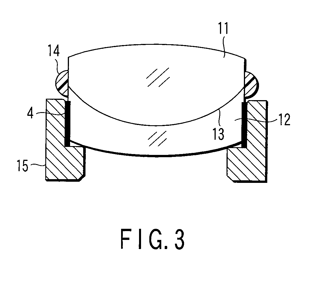
[0050]FIG. 3 is a cross-sectional view showing representative bonded lens in the objective lens of the fluorescence observing microscope. In this case, the first lens 11 and the second lens 12 are bonded together by making use of the silicone oil 13 of the aforementioned embodiment 2. A sealer is applied to the outer periphery of the bonded portion of bonded lens where the first lens 11 and the second lens 12 are contacted with each other. The clearance between the first lens 11 and a metallic mirror frame 15 is filled with the silicone adhesive 4 of the aforementioned embodiment 1, thereby fixedly bonding them.

[0051] Since the silicone adhesive 4 and the silicone oil 13 employed in this example were all formulated so as to minimize the contents of platinum group metallic catalyst, of multiple bond group, and of impurities such as transition metals and rare earth elements, it was possible to inhibit the generation of autofluorescence.

[0052] Especially, the silicone oil 13 employed...


PUM

PropertyMeasurementUnit
excitation wavelengthaaaaaaaaaa

Abstract

An optical device for fluorescence imaging equipped with a plurality of optical elements, wherein a silicone-based bonding agent containing a low-autofluorescent substance is interposed between the optical elements to bond the plurality of optical elements to each other.

Description

CROSS-REFERENCE TO RELATED APPLICATIONS [0001] This is a Continuation Application of PCT Application No. PCT / JP2005 / 011470, filed Jun. 22, 2005, which was published under PCT Article 21(2) in Japanese. [0002] This application is based upon and claims the benefit of priority from prior Japanese Patent Application No. 2004-185309, filed Jun. 23, 2004, the entire contents of which are incorporated herein by reference.BACKGROUND OF THE INVENTION [0003] 1. Field of the Invention [0004] This invention relates to an optical device for fluorescence imaging. In particular, this invention relates to an optical device for fluorescence imaging, such as a microscope for fluorescence imaging or an endoscope for fluorescence imaging, wherein ultraviolet excitation light is irradiated onto an object to be observed and the fluorescence emitted from the object is observed. [0005] 2. Description of the Related Art [0006] In resent years, in the field of biological imaging of organism such as a cell, g...

Claims


Application Information

Patent Timeline
Patent Type & Authority Applications(United States)
IPC IPC(8): A61B6/00
CPCC03C27/10G01N21/6458G01N21/6486G02B23/243G02B13/143G02B21/16G02B1/00
Inventor HAYASHI, TAKAEKINOSHITA, HIROAKI
Owner OLYMPUS CORP
Why Eureka
Try Eureka