
Nuclear fusion containment complex and systems network for the thermal durational enhancement of contained heat processes

a technology of containment complex and nuclear fusion, which is applied in the direction of nuclear reactors, nuclear engineering, greenhouse gas reduction, etc., can solve the problems of reactor safety and health risks, reactor waste, and alarming rate of depletion of raw materials of industry, so as to prolong the service life reduce the waste of the containment complex

Inactive Publication Date: 2007-07-26
GORDON EDWARD CADY II
View PDF2 Cites 5 Cited by
  • Summary
  • Abstract
  • Description
  • Claims
  • Application Information

AI Technical Summary

Benefits of technology

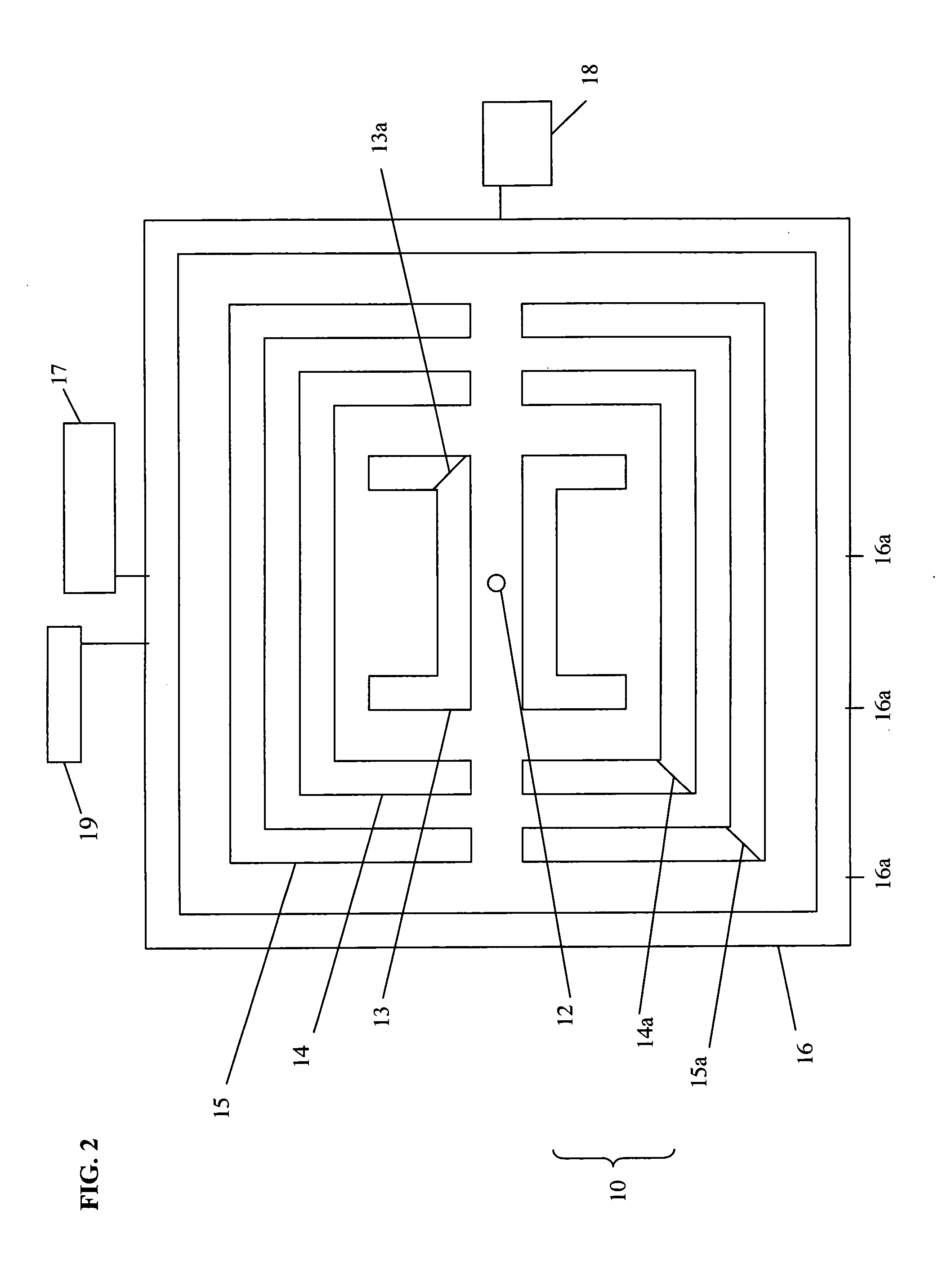
[0017] As all fusion (and fission) nuclear facilities and reactor systems generate radioactive waste (having life spans of between 5,000 to 100,000 years), the containment complex is to be insulated against premature contamination as well as heat loss. Therefore, it is contemplated that the thermal containment chambers of the containment complex have surfaces made of reinforced concrete plated on the exterior with plate steel that can be negatively or positively charged to restrict radioactive (positive or negative) charged particles from adhering to the wall, ceiling and floor surfaces of the containment complex. When a positively charged particle attempts to contact a (magnetically) positive charged surface, the positively charged surface restricts such contact. Furthermore, the plated walls may utilize variable conductive properties or materials related to conduct a suitable quantity of electrical charged energy at the wall surfaces so as to repel the positively or negatively charged particles. This would retard the tendency of the radioactive particles to adhere to the vessel walls, floor and ceiling. As a result, the suppression of radioactive contamination enhances the life of the complex.
[0024] The systems network can further include a wastewater treatment plant for processing of wastewater from the containment complex. It is to be noted that Granular Activated Carbon (GAC) can absorb radioisotopes with up to twenty-four minutes of contact time (i.e. time during which GAC is in contact with radioactive isotopes). Whereas the vessel's containment walls are electromagnetically charged to either positive or negative energy equivalents to repel charged radioactive particles, this would further offer a means by which direct restriction related to the contact of radioactive waste particles would be suspended in the air or in the vacuum space rather than adhere to the vessel walls. This would provide a means to restrict such direct radioactive contact directly with the vessel walls, thus retarding the tendency of the radioactive waste particles to adhere or impregnate the vessel walls. In an enhanced wall surface protected with plating, the advantages would be recognized by one of skill in the art. If waste particles cannot adhere to the vessel walls or other internal surfaces of the containment complex, the waste particles are restricted to the air or in the oxygen-depleted space internally held within the complex vessels' chambers. At maintenance intervals waste removal would employ flooding the containment complex with water, which would contain the radioactive waste by volume in terms of admixture, or as waste held in a solution by volume. The waste admixture would suspend and hold the radioactive waste particles in the water to be drained off as a waste discharge to be pumped to a wastewater treatment facility that utilizes GAC to adsorb the radioactive waste particles. In utilizing a wash cycle process to redirect radioactive waste particles from the containment complex to a GAC adsorption media, the waste deposit of the containment complex would be reduced. This would prolong the service life the containment complex. This would also offer a method of reclaiming the radioactive waste particles to be taken-up onto the GAC surfaces for collection adsorption, storage and waste remediation and containment. Further, it would provide as well a safe means of removal from the containment complex of the radioactive waste particles to be back-washed and held onto the GAC and removed safely from the facility, and or, be held as waste and for future fuel-feed-stock if desired. It is to be noted that temperature of GAC needs to remain below 110° so desorption will not occur.

Problems solved by technology

Nuclear power, the use of sustained nuclear reactions to do useful work, has long been recognized as a potentially limitless sustainable energy source.
Furthermore, the raw materials of industry, in the form of mineral concentrations accumulated through exceedingly slow geologic processes occurring over millions of years, are being depleted at an alarming rate.
However, such reactors are considered controversial for their safety and health risks.
Specifically, the production of radioactive waste has proven to be a highly controversial issue in the debate on nuclear energy, resulting in the fact that no new fission reactors have been built in the United States in the last several decades.
However, the use of magnetic confinement has proven to be difficult because the plasma generally exhibits some form of instability that prevents the magnetic field from being able to contain the heated, ionized gas for sufficient time to reach the breakeven point in energy production.
Neither of these methods has proven to be a viable method for harnessing fusion power.
However, such a system would require a massive supply of bombs (because of heat loss due to the heat permeating into the earth surface), making the feasibility of such a system doubtful.
The requirement of a massive number of nuclear bombs would also present a very serious security concern.

Method used


Image

  • Nuclear fusion containment complex and systems network for the thermal durational enhancement of contained heat processes
  • Nuclear fusion containment complex and systems network for the thermal durational enhancement of contained heat processes
  • Nuclear fusion containment complex and systems network for the thermal durational enhancement of contained heat processes

Examples


Embodiment Construction

[0029] In the following description of the preferred embodiments reference is made to the accompanying drawings, which are shown by way of illustration of specific embodiments in which the invention may be practiced. It is to be understood that other embodiments may be utilized and structural and functional changes may be made without departing from the scope of the present invention.

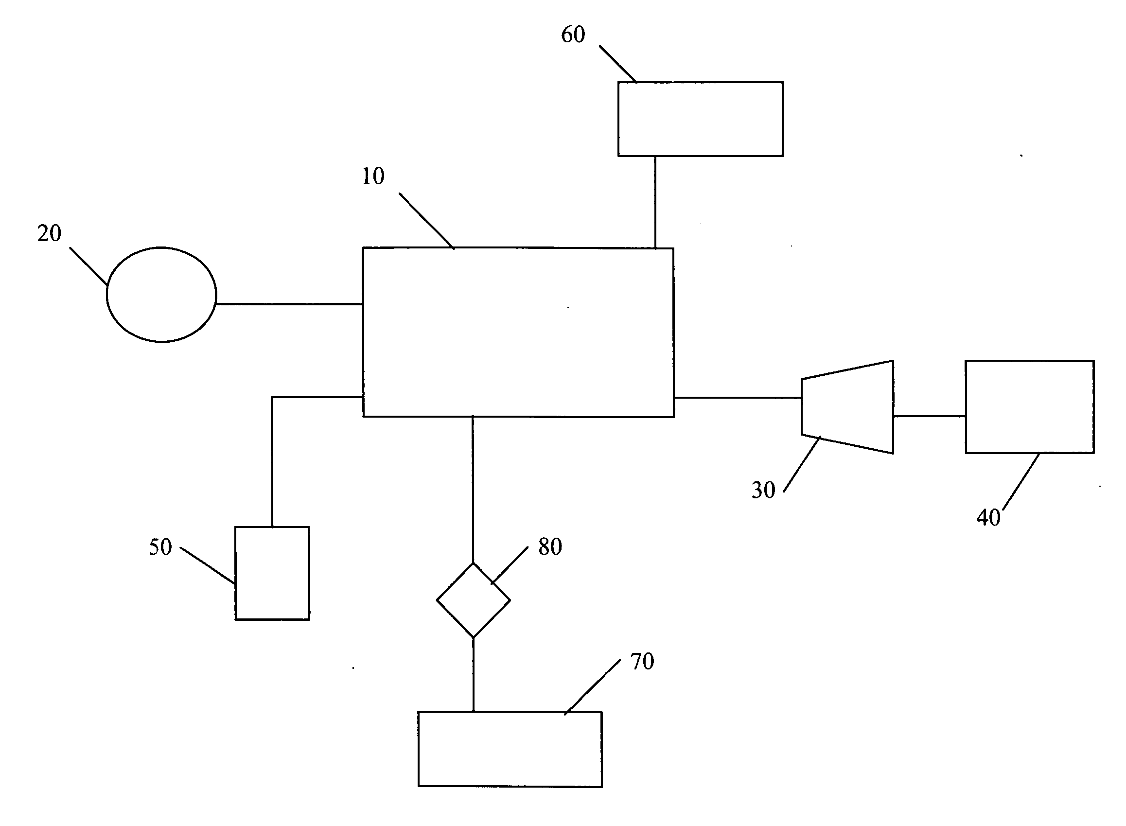
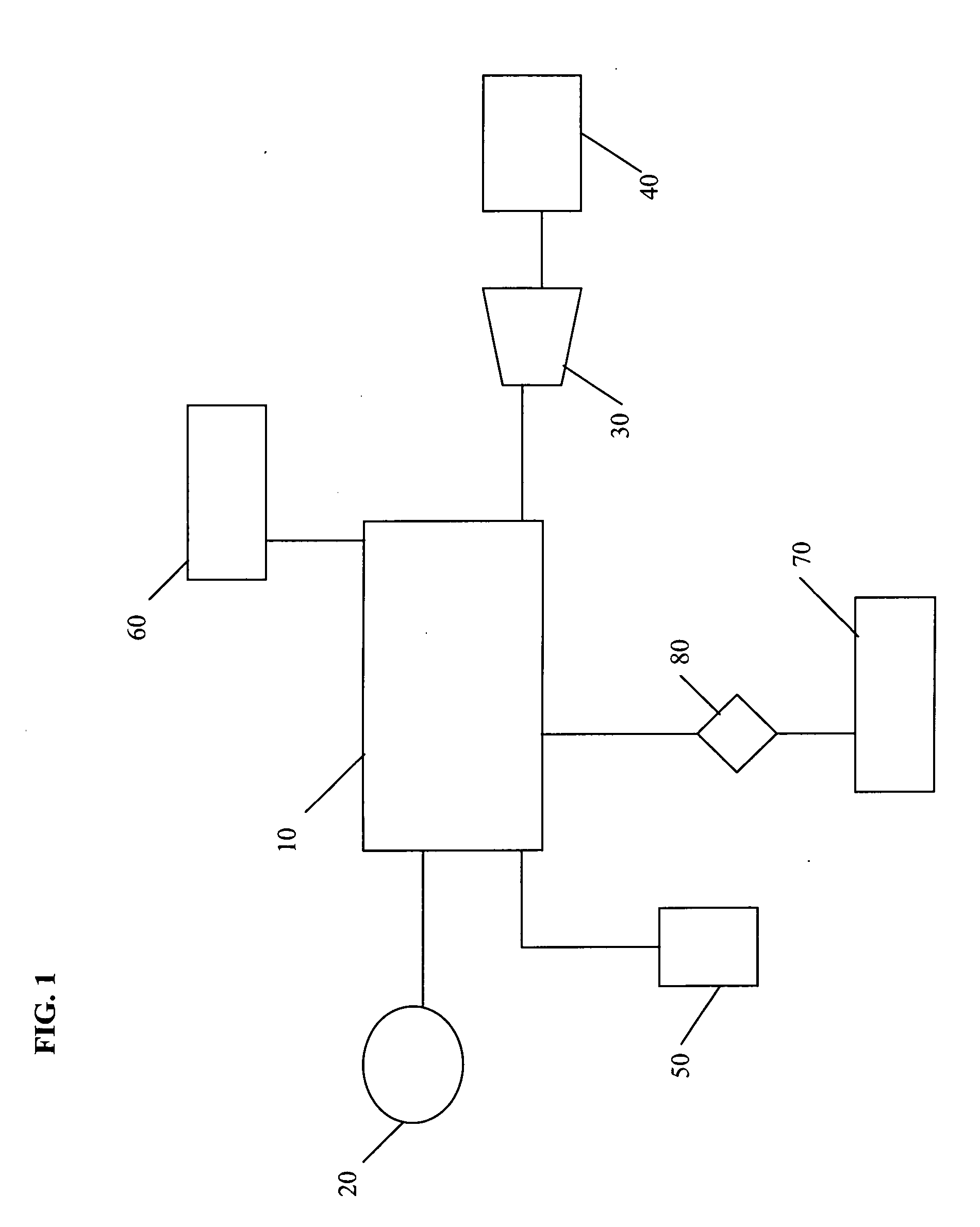
[0030] Referring to FIG. 1, at the center of a systems network (1) for harnessing nuclear fusion power is a containment complex (10). A nuclear reaction is generated in hydrogen detonation chamber (12) in containment complex (10). A feedwater plant (20) is connected to the containment complex (10), which supplies water for circulation in the containment complex (10). The circulated water in containment complex (10) is heated by the nuclear reaction in the containment complex (10). The nuclear reaction causes the water to be superheated, thereby converting the circulated water in containment complex (10...


PUM


Abstract

A systems network for harnessing nuclear fusion power and, more particularly, a complex for containment of a nuclear fusion detonation reaction, in which the nuclear detonation reaction is used to heat water for application in a steam turbine system that is used to drive a generator. The systems network include a feedwater plant, a steam turbine system, an oxygen producing plant, and a thermal recovery plant, connected to a containment complex having a hydrogen detonation chamber encased in a series of thermal containment chambers having electromagnetically charged walls and an outer structure.

Description

BACKGROUND OF THE INVENTION [0001] 1. Field of the Invention [0002] This invention relates generally to a system for harnessing nuclear fusion detonation power and, more particularly, to a containment complex for a nuclear fusion reaction, and method for containment and recovery of thermal energy to process steam production for electrical power generation. [0003] 2. Description of the Prior Art [0004] Nuclear power, the use of sustained nuclear reactions to do useful work, has long been recognized as a potentially limitless sustainable energy source. It is believed by some that nuclear power is an answer to the problems of dwindling oil reserves and the detrimental environmental effects of fossil fuel, such as Greenhouse gas emission that leads to global warming. Furthermore, the raw materials of industry, in the form of mineral concentrations accumulated through exceedingly slow geologic processes occurring over millions of years, are being depleted at an alarming rate. For instanc...

Claims


Application Information

Patent Timeline
IPC IPC(8): H05H1/22
CPCG21D7/00Y02E30/00
Inventor GORDON, EDWARD CADY II
Owner GORDON EDWARD CADY II
Learn More