Ultrafine polyactic acid fibers and fiber structure, and process for their production
a technology of polylactic acid fibers and fibers, applied in the field of fibers, can solve the problems of large environmental load, poor heat resistance of ultrafine fibers referred to above, and limited use, and achieve excellent heat resistance and biodegradability, and small fiber diameter
- Summary
- Abstract
- Description
- Claims
- Application Information
AI Technical Summary
Benefits of technology
Problems solved by technology
Method used
Image
Examples
example 1
[0089] After mixing 500 pp m of tin octylate with D-lactide, polymerization was conducted in a stirrer-equipped reactor at 200° C. for 60 minutes under a nitrogen atmosphere, to obtain a poly(D-lactic acid) homopolymer with a weight-average molecular weight of 120,000.
[0090] There were prepared a solution of 1 part by weight of the obtained poly(D-lactic acid) in 9 parts by weight of methylene chloride and a solution of 1 part by weight of poly(L-lactic acid) (Lacty 9031™ by Shimadzu Corp., weight-average molecular weight: 168,000) in 9 parts by weight of methylene chloride, and both solutions were mixed at 5 parts by weight each.
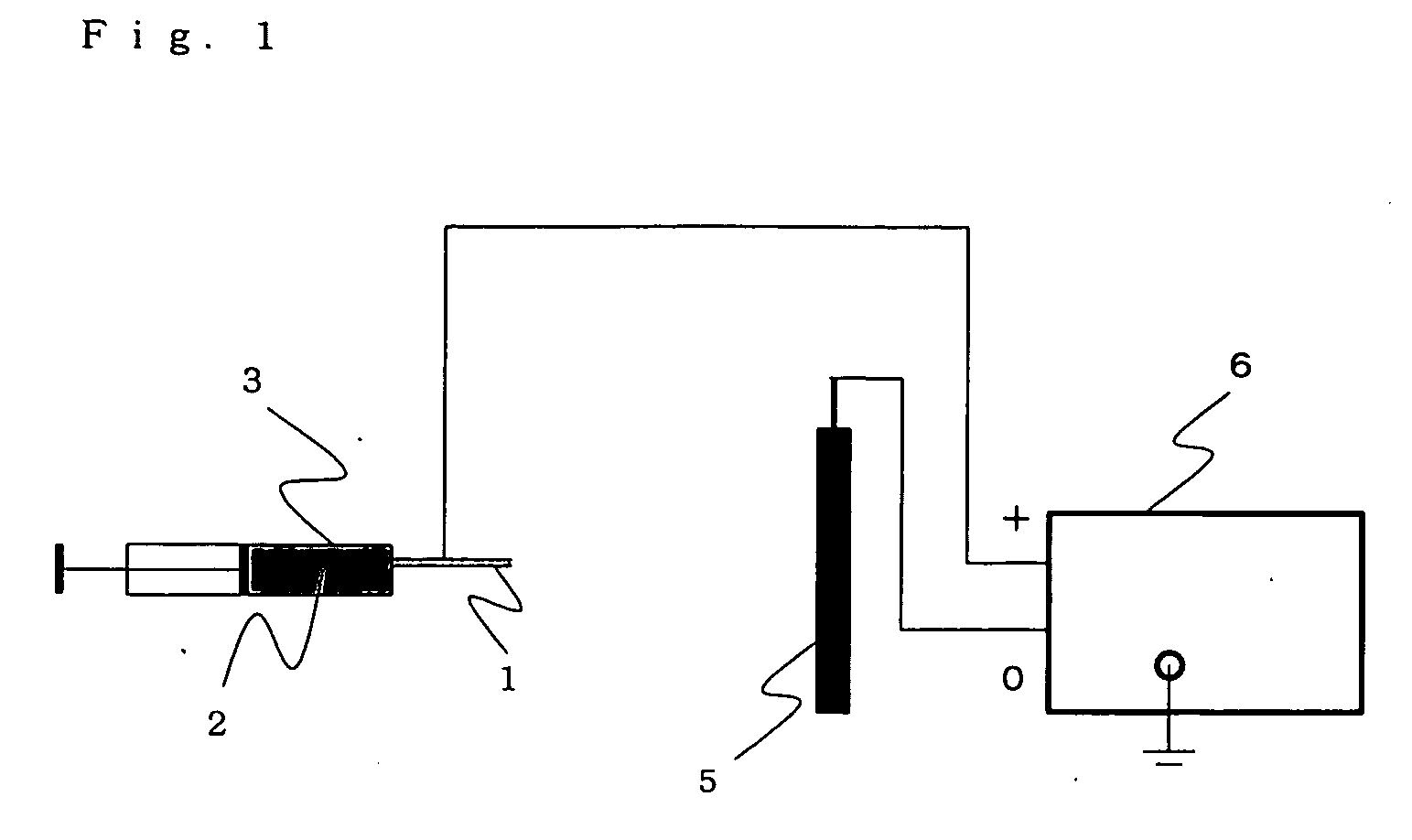
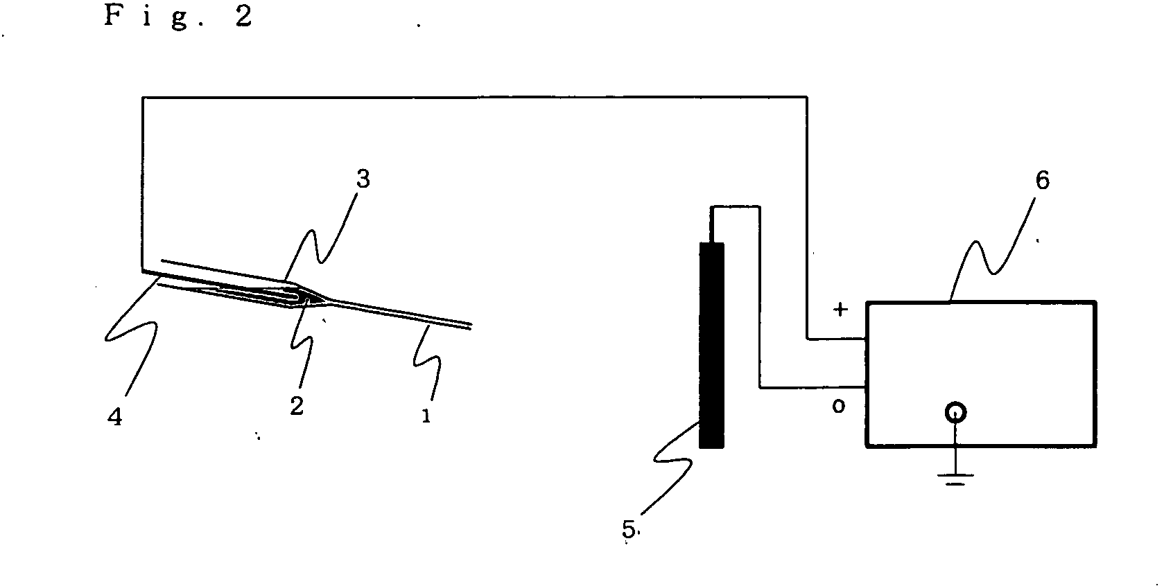
[0091] Next, the apparatus shown in FIG. 2 was used for discharge of the solution for 5 minutes onto a filamentous substance-collecting electrode 5. The inner diameter of the ejection nozzle (1 in FIG. 2) was 0.8 mm, the voltage was 12 kV, the distance from the ejection nozzle (1 in FIG. 2) to the filamentous substance-collecting electrode (5 in FIG. 2) w...
example 2
[0093] There were mixed 6 parts by weight of a solution of 1 part by weight of the poly(D-lactic acid) in 9 parts by weight of methylene chloride and 4 parts by weight of a solution of 1 part by weight of poly(L-lactic acid) in 9 parts by weight of methylene chloride, and a fiber structure was obtained in the same manner as Example 1, except that the distance from the ejection nozzle to the filamentous substance-collecting electrode was 10 cm.
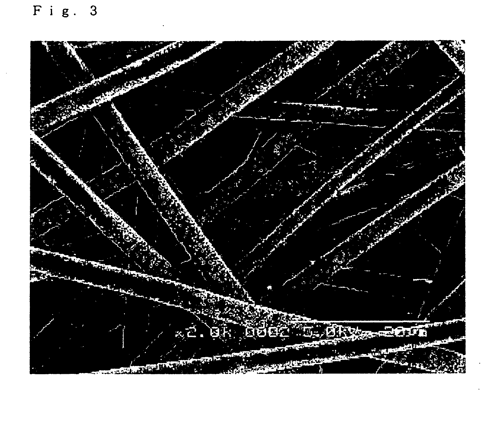
[0094] The mean fiber diameter of the obtained fiber structure was 4 μm, and no fibers were present with fiber lengths of less than 20 μm. The mean diameter of the depressions on the fiber surfaces was 0.2 μm, and the percentage of the fiber surface area occupied by the depressions was 22%. Scanning electron microscope photographs of the fiber structure are shown in FIGS. 5 and 6.
[0095] As a result of DSC measurement of the obtained fiber structure, the melting point was 218° C. and no endothermic peak was observed below 190° C.
example 3
[0105] A fiber structure was obtained in the same manner as Example 2, except that a methylene chloride / DMF mixed solvent (weight ratio: 8 / 2) was used instead of methylene chloride. The mean fiber diameter of the obtained fiber structure was 2 μm, and no fibers were present with fiber lengths of less than 20 μm. No fiber surface depressions were observed. Scanning electron microscope photographs of the fiber structure are shown in FIGS. 13 and 14.
[0106] As a result of DSC measurement of the obtained fiber structure, the melting point was 220° C. and no endothermic peak was observed below 190° C.
PUM
| Property | Measurement | Unit |
|---|---|---|
| lengths | aaaaa | aaaaa |
| lengths | aaaaa | aaaaa |
| melting point | aaaaa | aaaaa |
Abstract
Description
Claims
Application Information
 - R&D
- Intellectual Property
- Life Sciences
- Materials
- Tech Scout
- Unparalleled Data Quality
- Higher Quality Content
- 60% Fewer Hallucinations
Browse by: Latest US Patents, China's latest patents, Technical Efficacy Thesaurus, Application Domain, Technology Topic, Popular Technical Reports.
© 2025 PatSnap. All rights reserved.Legal|Privacy policy|Modern Slavery Act Transparency Statement|Sitemap|About US| Contact US: help@patsnap.com


