
Glass cloth and printed wiring board

a technology of glass cloth and printed wiring, which is applied in the direction of printed circuit aspects, weaving, other domestic objects, etc., can solve the problems of lowering productivity, inaccurate positioning of holes, and inferior insulation, and achieve the effect of enhancing the flattening of glass cloth

Inactive Publication Date: 2006-05-23
ASAHI SCHWEBEL
View PDF8 Cites 10 Cited by
  • Summary
  • Abstract
  • Description
  • Claims
  • Application Information

AI Technical Summary

Benefits of technology

[0011]The present inventors have diligently studied the above problem and found that it is necessary to specify a width of a cross-section of a glass fiber yarn and a weaving density of the glass cloth to unify the weave structure thereof in the surface direction for obtaining a laminated board excellent in surface smoothness which is indispensable for improving the processibility when a micro-hole is bored. This is particularly true when a laser beam is used, because the removal of a glass component is facilitated and the setting of proper process conditions is enhanced.
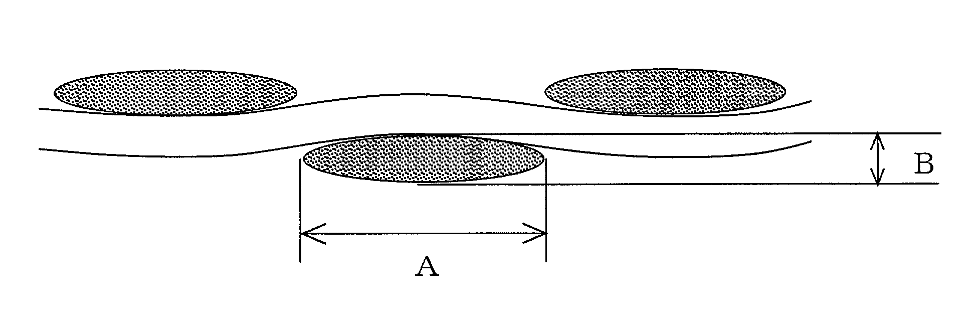
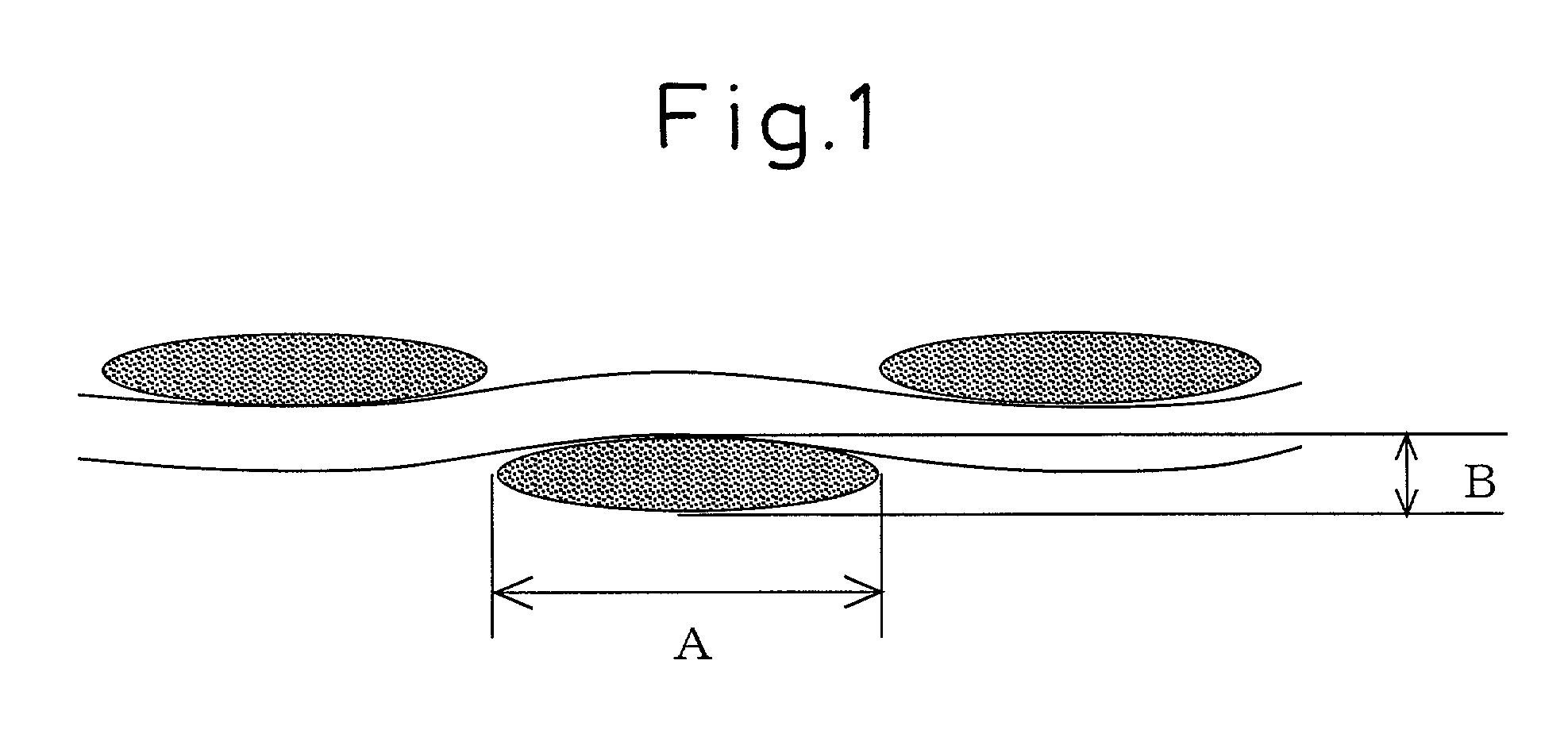
[0029]In other words, if both the warp and weft yarns have Ft of 0.75 or more, all the surface of the glass cloth is completely covered with the flattened warp and weft yarns, and thus the distribution of glass fibers in the glass cloth becomes uniform to facilitate the processibility thereof. Preferably, if Ft is 0.8 or more, the flattening is more sufficient and uniform.
[0035]The smaller a single-fiber diameter of the glass fiber yarn constituting the glass cloth, the easier the uniform dispersion of the fibers. Also, the smaller the fiber diameter, the smaller the boring resistance when the printed wiring board is bored by a drill. Further, when the laser beam is used, the removal of glass becomes easier. That is, a nominal diameter of a glass fiber is E or less, preferably D or less as defined by JIS-R-3413 in view of the boring of micro-holes.
[0037]The glass fiber yarn used for manufacturing the glass cloth according to the present invention is twisted at a smaller number of twists in a unit length in a range from 0.5 turns / 25 mm or less, preferably in a range from 0.3 to 0 turns / 25 mm than the conventional glass fiber yarn having the number of twists in a range from 0.7 to 1.0 turns / 25 mm. Thus, the twisted yarn can easily widen to form a fabric structure in which every adjacent yarn in the warp and weft is substantially in close contact with another with substantially no gap. Also, by using a yarn having a smaller number of twists, the yarn is liable to flatten so that the cross-section thereof approaches that of a flat sheet rather than an oval shape, whereby the distribution of the glass fibers in the glass cloth becomes more uniform.
[0038]The flattening of glass cloth may be enhanced by a fiber-opening process, for example, by the application of hydraulic pressure due to a water flow, the high-frequency vibration through a liquid medium, the injection of fluid having a surface pressure or the roll pressure, whereby the width of the twisted yarn becomes more broad to result in a fabric structure in which adjacent yarns are arranged with substantially no gap in both the warp- and weft-wise directions. Also, the yarn is flattened to have a cross-section similar to that of a flat sheet rather than an oval shape, whereby the distribution of the glass fibers in the glass cloth becomes more uniform, which effect is the same as that obtained by using a yarn having a smaller number of twists. Moreover, a glass cloth prepared from glass fiber yarns applied with an organic lubricant or having a binder or a sizing agent conventionally used in the weaving process (a so-called gray fabric) may be effectively flattened by the combination of these means. Also, a combination of both the means is particularly effective.
[0040]While a so-called E glass (non-alkali glass) is generally used for preparing a glass cloth of a laminated board for a printed wiring board or others, D glass, S glass or high-dielectric constant glass may be used without deteriorating the effect of the present invention.

Problems solved by technology

However, when the diameter of the hole is reduced, and a conventional boring method is used, there are problems in that an inner wall of the bored hole is rough, a position of the hole is inaccurate, and inferior insulation may occur due to the entrance of a plating solution, used in the post plating process, through the inner wall of the hole.
However, when a drill corresponding to such a small hole is used, it is easily broken and must be frequently replaced, resulting in a lowering of the productivity.
In addition, since the thickness of the insulation substrate is reduced to 0.1 mm or less because of the miniaturization of the printed wiring board, it is difficult to control the depth of the hole to an accuracy of 0.1 mm or less if a drill is used.
However, since this build-up wiring board generally has no glass cloth, the dimensional stability and the heat durability are largely degraded, and since a process different from the conventional process is necessary for forming a build-up layer, the production cost is high.
Accordingly, the respective materials are unevenly processed during the boring with a laser beam to roughen the inner wall of the hole and deteriorate the reliability of the plating conductivity.
However, in the insulation substrate in which the organic matrix resin and the inorganic glass cloth are unevenly distributed in the surface direction, an improvement in process uniformity of the bored holes has not yet been achieved.
Accordingly, the uniformity of the respective holes is improved but the processibility is lowered due to the increase in an amount of glass, which also results in an increase in cost.

Method used


Image

  • Glass cloth and printed wiring board
  • Glass cloth and printed wiring board

Examples


example 1

[0055]A glass cloth was woven by an air jet loom from warp and weft yarns of C1200 1 / 0 1.0 Z at a warp density of 69 ends / 25 mm and a weft density of 69 ends / 25 mm. The resultant gray fabric was continuously subjected to a flattening treatment through a press roll at a line pressure of 300 N / cm and then to a fiber-opening treatment by a high-pressure water spray at a pressure of 200N / cm2. Thereafter, the glass cloth was desized at 400° C. for 24 hours.

[0056]Subsequently, the glass cloth was dipped into a solution of silane coupler (SZ6032, manufactured by Toray•Dow Corning K.K.) as a surface treatment agent, squeezed and dried at 120° C. for 1 minute to result in the finished glass cloth having a basis weight of 24 g / m2 and a thickness of 0.028 mm. Therefrom, a laminated board was prepared as described above.

example 2

[0057]A glass cloth was woven by an air jet loom from warp and weft yarns of C900 1 / 0 1.0 Z at a warp density of 69 ends / 25 mm and a weft density of 69 ends / 25 mm. The resultant gray fabric was subjected to a fiber-opening treatment by a high-pressure water spray at a pressure of 200N / cm2. Thereafter, the glass cloth was desized at 400° C. for 24 hours.

[0058]Subsequently, the glass cloth was subjected to a surface treatment in the same manner as in Example 1 to result in the finished glass cloth having a basis weight of 30 g / m2 and a thickness of 0.030 mm. Therefrom, a laminated board was prepared as described above.

example 3

[0059]A glass cloth was woven by an air jet loom from warp and weft yarns of D900 1 / 0 1.0 Z at a warp density of 69 ends / 25 mm and a weft density of 69 ends / 25 mm. The resultant gray fabric was subjected to a fiber-opening treatment by a high-pressure water spray at a pressure of 150N / cm2. Thereafter, the glass cloth was desized at 400° C. for 24 hours.

[0060]Subsequently, the glass cloth was subjected to a surface treatment in the same manner as in Example 1 to result in the finished glass cloth having a basis weight of 30 g / m2 and a thickness of 0.032 mm. Therefrom, a laminated board was prepared as described above.


PUM

PropertyMeasurementUnit
thicknessaaaaaaaaaa
thickaaaaaaaaaa
thicknessaaaaaaaaaa

Abstract

The present invention is(1) a glass cloth composed of a group of warp yarns and a group of weft yarns wherein one of the group of the warp and weft yarns are arranged with substantially no gap between the yarns, and, in that group, a width A (μm) of a cross-section of the yarn arranged with substantially no gap, a single-fiber diameter L (μm) of the yarn, the number N of single-fibers constituting the yarn and a weaving density C (ends / 25 mm) of the glass cloth composed of the yarns satisfy the following equation (1-a):C×A / (25×L×N)≧1.0, and   (1-a)(2) a glass cloth composed of a group of warp yarns and a group of weft yarns wherein both of the groups of the warp and weft yarns are arranged with substantially no gap between the yarns, and, in both the groups, a width A (μm) of a cross-section of the yarn, a single-fiber diameter L (μm) of the yarn, the number N of single-fibers constituting the yarn and a weaving density C (ends / 25 mm) of the glass cloth satisfy the following equation (1-b):C×A / (25×L×N)≧0.75.   (1-b)The glass cloth according to the present invention is useful as a substrate for a printed wiring board. The printed wiring board using the glass cloth of the present invention as a substrate is capable of being bored with a laser beam to produce micro-holes (the roughness of the inner wall, the reproducibility and the roundness of the micro-holes are improved) therein, especially, is able to prepare uniform and small via-holes which are recently required for high-density wiring.

Description

TECHNICAL FIELD[0001]The present invention relates to a printed wiring board used in the electronic and electrical fields and, particularly, to a high density printed wiring board with small-diameter holes bored therein and to a glass cloth used therefor.BACKGROUND ART[0002]A printed wiring board, particularly a laminated printed wiring board, is constituted by laminating a plurality of insulating substrates, each carrying a conductive layer, with each other. The conductive layer provided between the insulation substrates is electrically connected to other optional conductive layers positioned on the upper or lower insulation substrates via conductive holes called through-holes, inner holes or blind holes. On the other hand, corresponding to the recent development of high performance and small-sized electronic equipments, a printed wiring board must be densely loaded with electronic elements. For the purpose of increasing the wiring density, the diameters of the via holes must be re...

Claims


Application Information

Patent Timeline
Patent Type & Authority Patents(United States)
IPC IPC(8): D03D15/00H05K1/03
CPCD03D15/0011H05K1/0366Y10S428/901H05K2201/029Y10T442/3065Y10T442/3089Y10T442/3114D03D15/267D03D13/008D03D1/0082D10B2101/06
Inventor KIMURA, YASUYUKIGONDOH, YOSHINORIFUJIMURA, YOSHINOBU
Owner ASAHI SCHWEBEL
Learn More