Sequential batch reactor wastewater treatment process

a batch reactor and wastewater technology, applied in the direction of water treatment parameter control, water/sludge/sewage treatment, moving filter element filter, etc., can solve the problems of large installation cost, major contributor to operation cost, and most of this water is too salty to be of any use, so as to improve energy efficiency, improve the effect of biological nutrient removal, and improve the effect of accuracy and precision

Inactive Publication Date: 2007-08-02
VISION ENVIROTECH INT
View PDF1 Cites 16 Cited by
  • Summary
  • Abstract
  • Description
  • Claims
  • Application Information

AI Technical Summary

Benefits of technology

[0012] The present invention comprises an improved SBR wastewater treatment system utilizing advanced process control. Advanced process control allows the SBR treatment process to achieve not only removal of organic carbon and suspended solids, but also to enhance biological nutrient removal. In additi

Problems solved by technology

While water covers approximately two-thirds of the planet, most of this water is too salty to be of any use.
Although this BNR configuration can provide advanced secondary wastewater treatment with nutrient removal, their large land footprint and high cost often prohibit their installation, especially in decentralized applications where sewer mains are not already established.
For larger wastewater treatment plants, energy costs are a major contributor to operation costs and can amount to many hundreds of thousands of dollars per year.
Nevertheless, one shortcoming of biological treatment processes that is inherent to both activated sludge and SBR processes at large is the lack of advanced process control.
Over-aeration leads to excessive energy consumption as well as compromised sludge pe

Method used


Image

  • Sequential batch reactor wastewater treatment process
  • Sequential batch reactor wastewater treatment process
  • Sequential batch reactor wastewater treatment process

Examples


Embodiment Construction

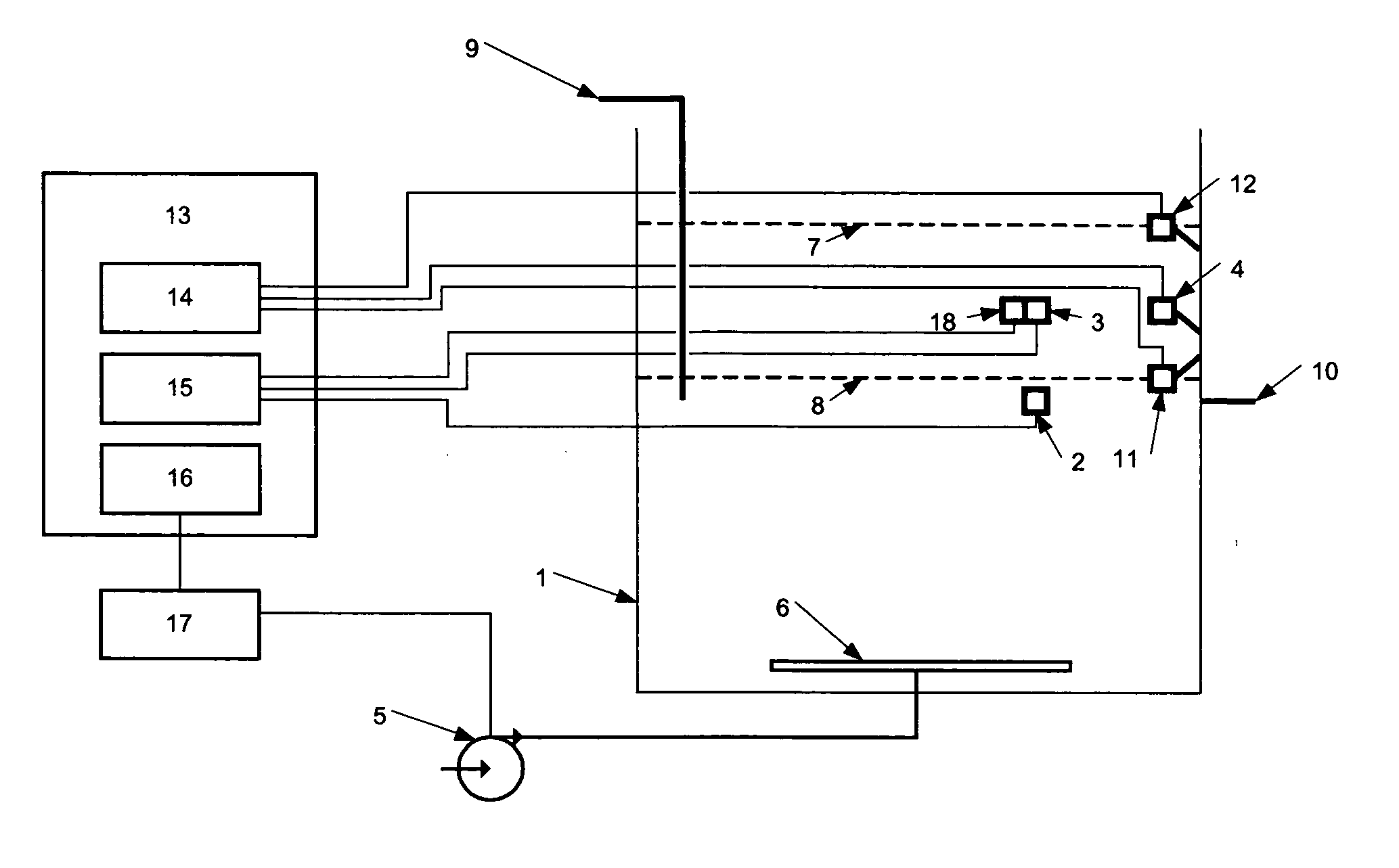
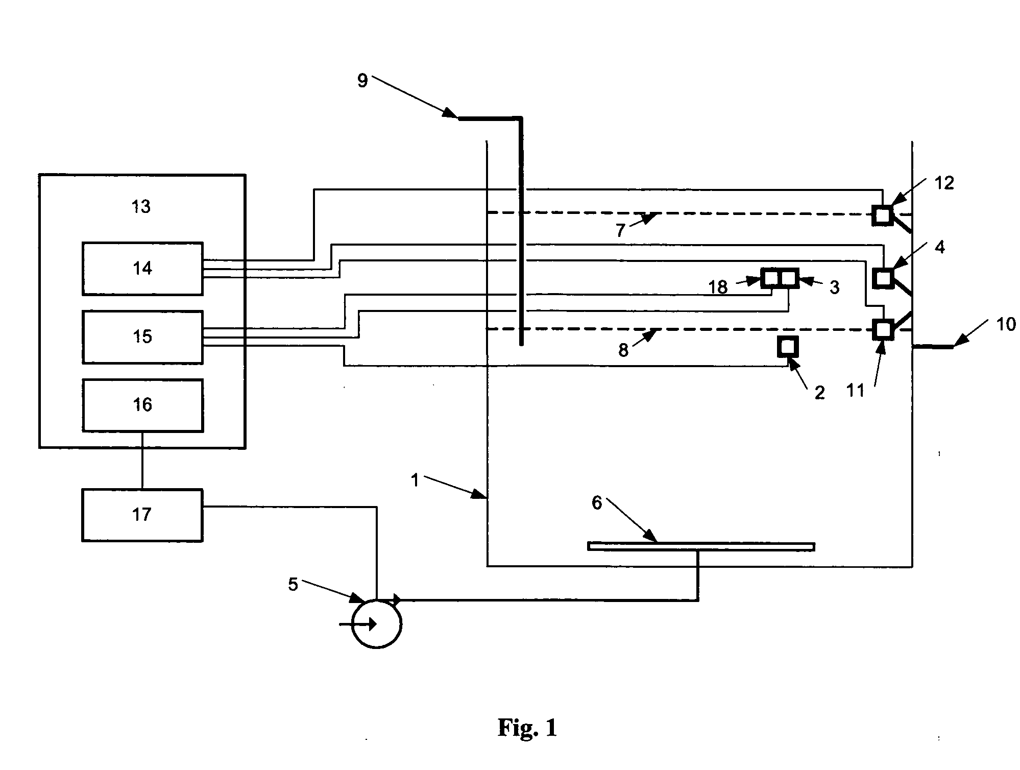
[0022] The preferred embodiment of an improved SBR wastewater treatment system according to the invention is generally illustrated in FIG. 1.

Equipment

[0023] During the fill phase, wastewater to be treated is placed in a tank 1 having a high water level 7 and a low water level 8. The high water level 7 is located at the height at which the tank 1 is at maximum capacity. After the tank 1 is decanted (i.e. the clarified liquid removed), the water is at the low water level 8. The tank 1 is equipped with an inlet 9 through which wastewater enters the tank 1 and an outlet 10 through which effluent exits the tank 1. An upper DO sensor float switch 4 mounted in tank 1 monitors the level of wastewater in the tank 1. A low level float switch 11, a high level float switch 12, a lower DO sensor 2, and an upper DO sensor 3 are also installed in the tank 1. When the water reaches the upper DO sensor float switch 4 during filling, a signal is sent to the programmable logic controller (PLC) 13 t...


PUM

PropertyMeasurementUnit
Angleaaaaaaaaaa
Concentrationaaaaaaaaaa
Levelaaaaaaaaaa

Abstract

A system for controlling the aerobic phase of a wastewater treatment cycle in a sequencing batch reactor, comprising a tank, an air blower, at least one sensor for measuring the concentration of dissolved oxygen in the tank, and means to control the length of time that the air blower introduces air into the wastewater and to maintain at a constant level the volume of air introduced per time by the air blower. The length of time that the air blower introduces air is determined by the change in the slope of the curve representing the concentration of dissolved oxygen in the wastewater. The volume of air to be introduced per time by the air blower is determined based on the average concentration of dissolved oxygen from the previous wastewater treatment cycle.

Description

FIELD OF THE INVENTION [0001] The present invention relates to the treatment of wastewater. More particularly it relates to a system for the biological treatment of municipal and industrial wastewater through the control of aerobic microbial processes. BACKGROUND OF THE INVENTION [0002] While water covers approximately two-thirds of the planet, most of this water is too salty to be of any use. As the demand for water continues to increase along with a growing world population, the treatment of wastewater has become ever more important. [0003] Conventional biological wastewater treatment processes typically utilize an activated sludge configuration and incorporate at least two tanks: an activated sludge reactor and a secondary clarifier. This activated sludge process is used to treat organic carbon (e.g. measured as BOD, or biochemical oxygen demand) and suspended solids. The secondary clarifier is required in order to remove sludge and suspended solids. [0004] To achieve advanced tr...

Claims


Application Information

Patent Timeline
IPC IPC(8): C02F3/02
CPCC02F3/006C02F3/1263C02F2209/42C02F2209/38C02F2209/22Y02W10/10
Inventor CHEUK, WILLIAMLAU, ANTHONYWONG, RAYMONDDOIG, PETERFRASER, BUD
Owner VISION ENVIROTECH INT
Why Eureka
Try Eureka