Paired ZF Sampling for Pulse Running Time Filling Level Sensor

a level sensor and pulse running time technology, applied in the field of level measurement, can solve the problems of affecting the dynamic range, the amplitude difference between the echoes of well reflecting surfaces at the close range and the echoes of poorly reflecting surfaces at the end of the measurement range may be very large, and the dynamic range cannot be managed. to avoid undesirable dc components

Active Publication Date: 2007-08-16
VEGA GRIESHABER GMBH & CO
View PDF33 Cites 43 Cited by
  • Summary
  • Abstract
  • Description
  • Claims
  • Application Information

AI Technical Summary

Benefits of technology

[0024]In order to avoid undesirable DC components in the sampled IF signal, it may be appropriate, to place the interval ta2 between the sampling pairs approximately half-way between two forbidden areas. Then, through digital band-pass filtering of all digital values of an IF curve, both an interfering DC component and other interfering signals, e.g. noise, close to the IF frequency band can be eliminated. Such digital band-pass filtering can be applied e.g. separately to respectively the group of all first sampling values of all pairs and the group of all second values of all pairs of the IF curve.

Problems solved by technology

Due to the analog construction of both channels, certain problems caused by component tolerances and long term drift appear in signal processing, which may lead to a decrease in measuring accuracy.
Furthermore, it has to be noted that the amplitude differences between echoes of well reflecting surfaces at close range and poorly reflecting surfaces at the end of the measurement range may be very large.
If for envelope formation, the common method of half or full wave rectification is used, e.g. via analog diode circuits, with subsequent low-pass filtering, such a dynamic range can hardly be managed.
However, the requirements regarding the necessary sampling frequency, the amplitude resolution of A / D conversion, and the memory and computing load of digital signal processing may be problematic.
However, on the analog side in turn, more circuit means may be required.

Method used


Image

  • Paired ZF Sampling for Pulse Running Time Filling Level Sensor
  • Paired ZF Sampling for Pulse Running Time Filling Level Sensor
  • Paired ZF Sampling for Pulse Running Time Filling Level Sensor

Examples


Embodiment Construction

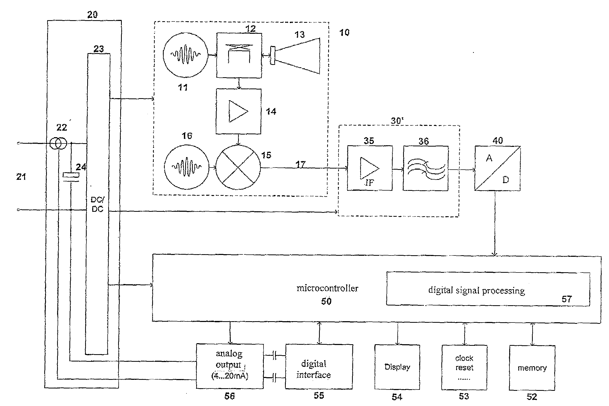
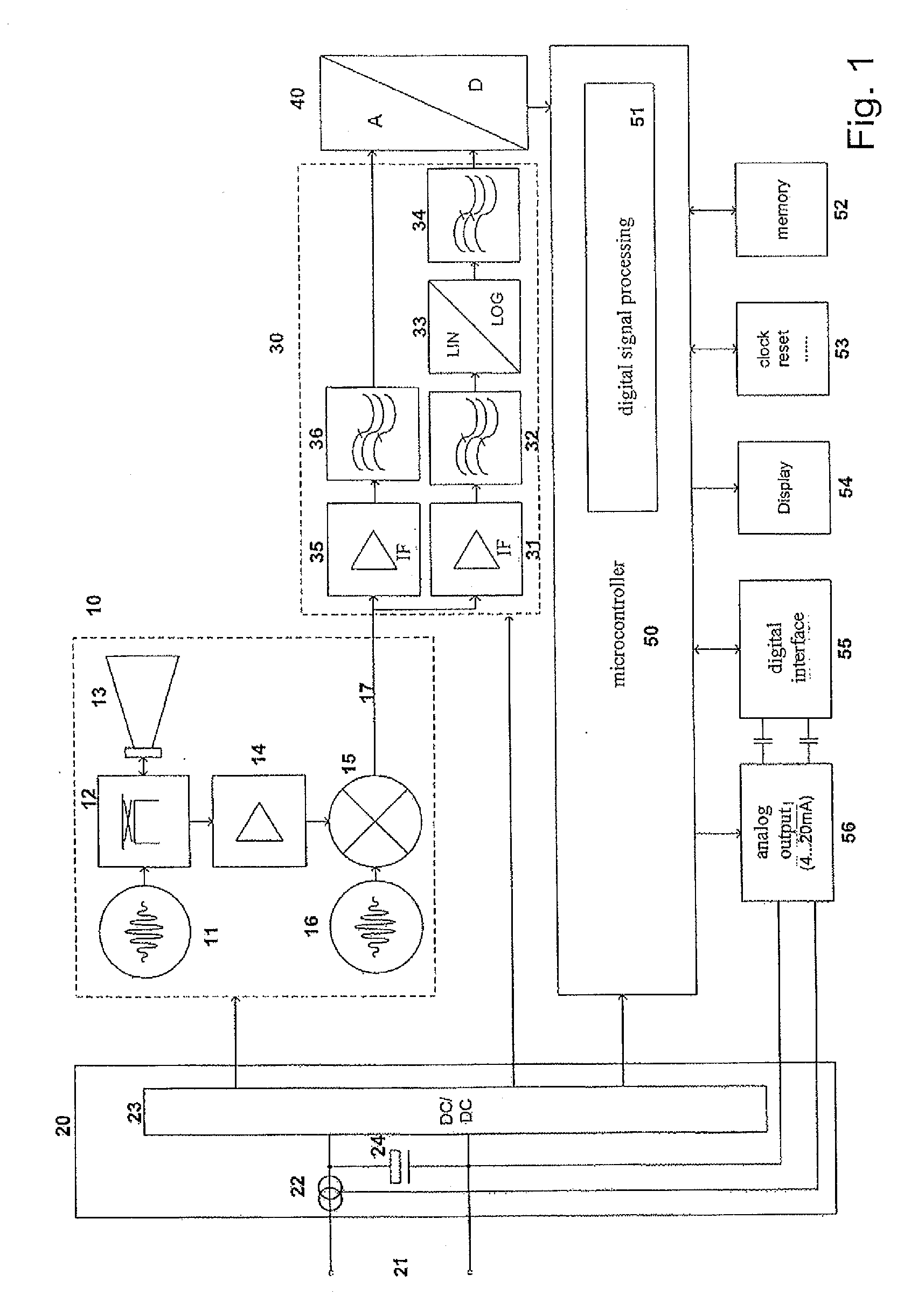
[0075]FIG. 1 shows a radar filling level sensor, operating according to the pulse running time method, with a high frequency circuit section 10, a power unit 20, analog signal processing 30, an A / D converter 40, and a microcontroller 50 with peripherals, e.g. memory 52, display 54, clock and reset circuit 53. The sensor is supplied for instance via the two-wire circuit 21, which also outputs the filling level value in analog form, applied by the power source 22 and the controller 56, as a current of 4 . . . 20 mA. On the supply line 21, digital communication of the sensor with the outside may also take place simultaneously. Materially, this may be made possible by means of the digital interface 55. As is known to those skilled in the art, the power unit contains a DC / DC converter 23 with series-connected memory capacitor 24 for supplying all other circuit sections.

[0076]The high frequency circuit 10 contains a transmit generator 11 for generating high frequency transmit pulses with ...


PUM


Abstract

A pulse running time filling level sensor includes a sampling device for sampling an IF signal at discrete instants and for converting the sampling values into digital sampling values, and a digital signal processing device for subsequent processing of the digital sampling values by calculating at least one new value characterizing the IF curve from respectively exactly two digital sampling values.

Description

REFERENCE TO RELATED APPLICATIONS[0001]This application claims the benefit of the filing date of German Patent Application Serial No. 10 2006 006 572.7 filed Feb. 13, 2006 and U.S. Provisional Patent Application Ser. No. 60 / 772,701 filed Feb. 13, 2006, the disclosure of which applications is hereby incorporated herein by reference.FIELD OF THE INVENTION[0002]The present invention relates to level measuring. In particular, the present invention relates to a method for level measuring for a pulse running time filling level sensor, and a level measuring instrument, which determines the filling level of a filling material in a container according to the pulse running time method.BACKGROUND INFORMATION[0003]For continuous filling level determination in containers, containing e.g. liquids or bulk materials, frequently sensors are used, which measure according to the pulse running time method the running time of electromagnetic or sound waves from sensor to filling material surface and bac...

Claims


Application Information

Patent Timeline
Patent Type & Authority Applications(United States)
IPC IPC(8): G01F17/00G01F23/00
CPCG01F23/284G01F23/2962G01S7/285G01S15/88G01S7/5273G01S13/103G01S13/88G01S7/2922G01F23/266G01F23/282G01F23/80G01F23/804
Inventor GRIESSBAUM, KARLFEHRENBACH, JOSEFWELLE, ROLANDHAAS, JUERGEN
Owner VEGA GRIESHABER GMBH & CO
Why Eureka
Try Eureka