Integrated wavelength selective grating-based filter

a wavelength selective filter and integrated technology, applied in the field of wavelength selective filters, can solve problems such as enlarging the overall dimension of devices, and achieve the effect of low coupling loss and simple connection between the integrated filter and the standard external fiber of the transmission system

Inactive Publication Date: 2007-08-16
PIRELLI & C
View PDF6 Cites 13 Cited by
  • Summary
  • Abstract
  • Description
  • Claims
  • Application Information

AI Technical Summary

Benefits of technology

[0028] Applicants have focused their attention on wavelength-selective filters comprising grating structures and realized on planar waveguides. One of the goals of the present invention is to realize an integrated-optical filter in which the connection between the integrated filter and a standard external fiber of a transmission system is simple and has low coupling losses.

Problems solved by technology

Additionally, in order to obtain the same performances of a filter comprising a planar waveguide, the same filter including a ridge waveguide needs longer gratings, thus enlarging the device's overall dimensions.

Method used


Image

  • Integrated wavelength selective grating-based filter
  • Integrated wavelength selective grating-based filter
  • Integrated wavelength selective grating-based filter

Examples


example 1

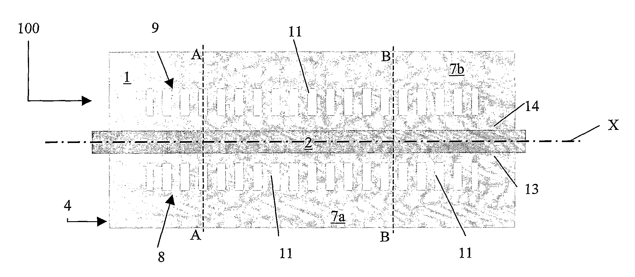
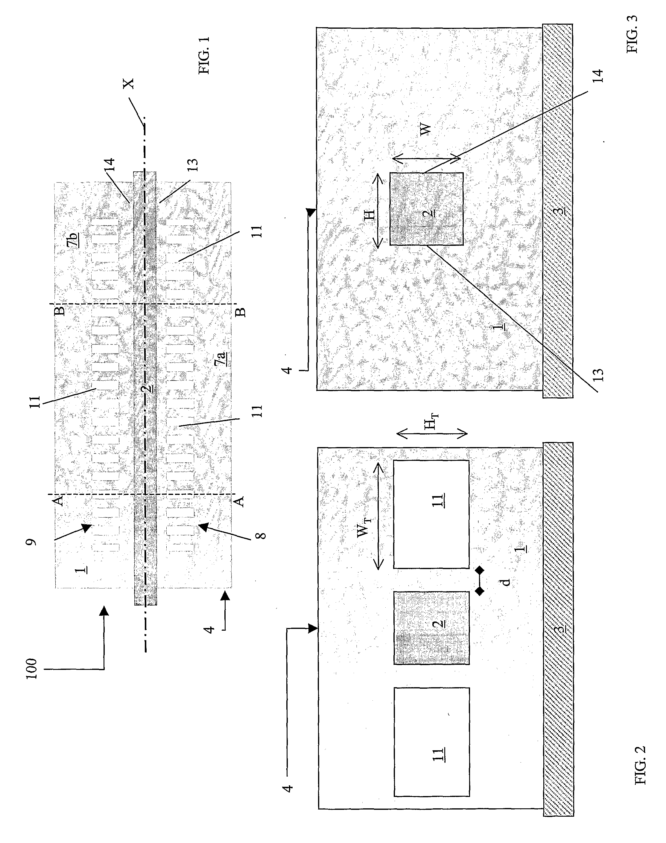
[0098] With reference to FIGS. 1-3 and 15, the lower cladding 5 is realized in SiO2 with a thickness of 10 μm and a refractive index of nlower=1.446, and it is deposited on a silicon wafer 3.

[0099] The core 2, having a 4.5×4.5 μm2 cross-section, is realized in Ge-doped SiO2 (ncore=1.456).

[0100] The lateral cladding 7 is realized in BPSG, having a refractive index of nlateral=1.446.

[0101] The upper cladding 6, having a thickness of 10 μm, is realized in SiO2.

[0102] The first and second plurality 8, 9 of grating trenches 11 forming the grating structure have a width WT of 3 μm and a height HT of 4.5 μm, and are filled with air (nair=1). Therefore the refractive index difference is ΔnG=0.446.

[0103] The distance of the trenches 11 from the core is d=500 nm. The grating period is equal to 536 nm with a duty cycle of 50%.

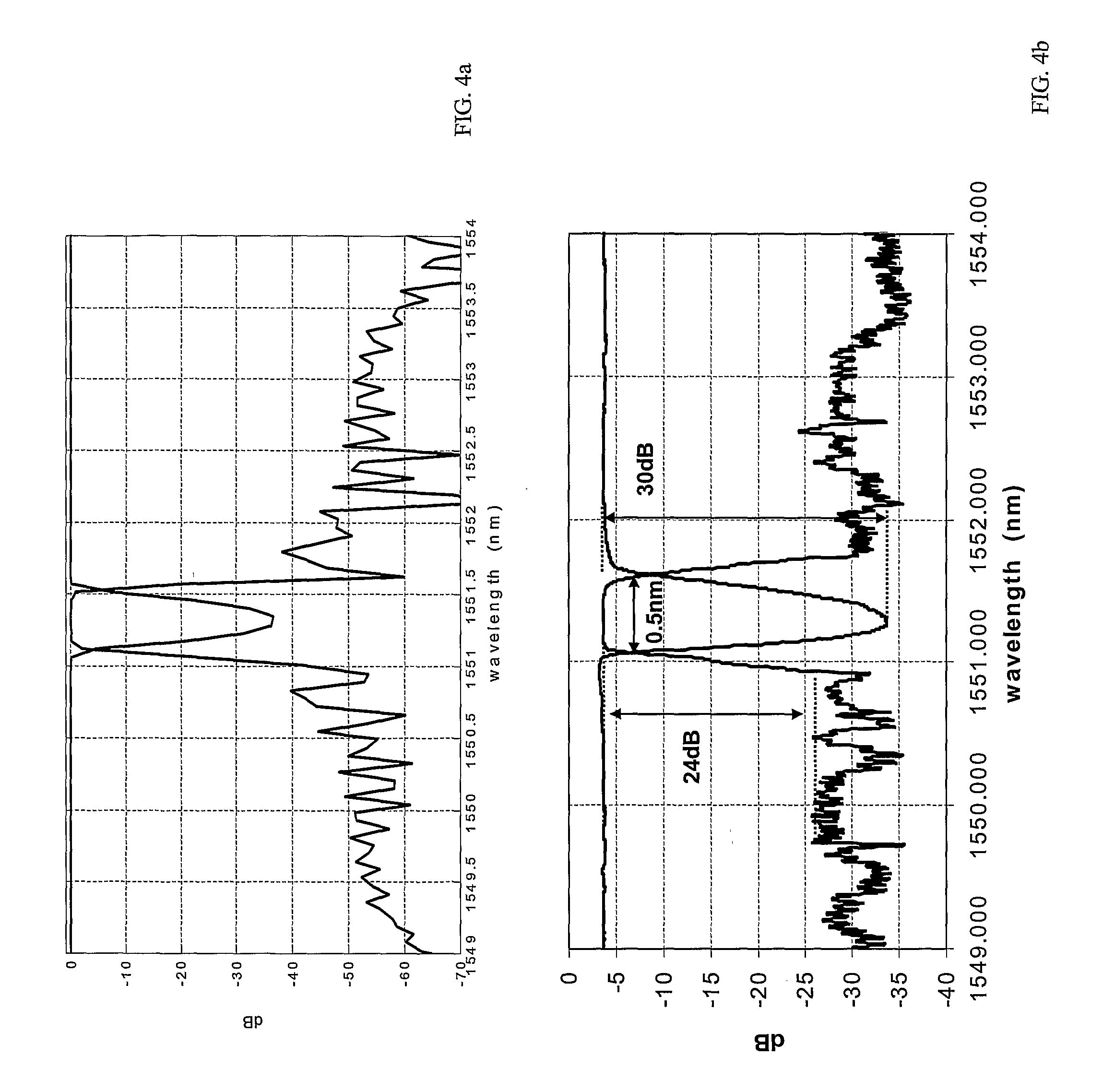
[0104] Considering an input signal applied to an input port 21 of the filtering element 100 comprising a plurality of channels having wavelengths spaced apart as de...

example 2

[0127] A filtering element 100 is realized following the process outlined below.

[0128] On top of a silicon wafer 3, a SiO2 layer (the lower cladding 5) is realized by thermal oxidation, having a thickness of 10 μm. On top of this layer, a core layer 2′ which is made of Ge-doped SiO2 and which has a thickness of 4.4 μm, is deposited using PECVD.

[0129] The core layer 2′ is thus covered by a polysilicon layer 12, 0.5 μm thick, deposited using LPCVD. The polysilicon layer 12 and the core layer 2′ are thus patterned using a dry etching technique.

[0130] The BPSG lateral cladding layer 7′ is then deposited by Atmospheric Pressure Chemical Vapour Deposition (APCVD) on top of the core 2 and lower cladding 5, with an initial thickness of 8.5 μm, and it is then planarized using CMP. The BPSG layer in excess is then removed through etching (etchback phase) up to the core height.

[0131] The portion of polysilicon layer remained on top of the core 2 is thus removed.

[0132] The trenches 11 are ...


PUM


Abstract

A wavelength selective grating-based filter includes a planar waveguide which includes a core surrounded by a cladding, the cladding including a lower cladding, the core being placed above the lower cladding, a lateral cladding adjacent to a first and a second opposite lateral sides of the core, and an upper cladding, said upper cladding being positioned above said core and lateral cladding. The waveguide also includes a grating structure, including a first and a second plurality of grating trenches formed in the lateral cladding in proximity of the first and second opposite lateral sides of the core, respectively. The first and second plurality of grating trenches are covered by the upper cladding.

Description

TECHNICAL FIELD [0001] The present invention relates to a wavelength selective filter comprising a grating, and it is directed in particular to the realization of integrated wavelength division multiplexer / demultiplexer optical devices in which light at a specific wavelength (or specific wavelengths) can be added or dropped in an efficient manner. TECHNOLOGICAL BACKGROUND [0002] Wavelength division multiplexed (WDM) or dense WDM (DWDM) optical communication systems, require the ability to passively multiplex and demultiplex channels at certain network nodes and, in some architecture, to add and drop channels at selected points in the network, while allowing the majority of the channels to pass undisturbed. [0003] Diffraction gratings, for example Bragg gratings, are used to separate the independent optical channels, which have different transmission wavelengths and are transmitted along a line, by reflecting one wavelength into a separate optical path, while allowing all other wavel...

Claims


Application Information

Patent Timeline
Patent Type & Authority Applications(United States)
IPC IPC(8): G02B6/34
CPCG02B6/124
Inventor TORMEN, MAURIZIOROMAGNOLI, MARCO
Owner PIRELLI & C
Why Eureka
Try Eureka