Liquid discharge recording head and liquid discharge apparatus

a liquid discharge recording and liquid discharge technology, applied in printing and other directions, can solve the problems of difficult to realize high accuracy with such a mechanical device, difficult to perform the bonding process with the substrate having ink-discharge-pressure-generating elements, and difficult to produce uniform orifice plates, etc., to achieve excellent durability, reduce stress in the covering resin layer, and prevent crack generation

Inactive Publication Date: 2007-08-23
SONY CORP
View PDF1 Cites 3 Cited by
  • Summary
  • Abstract
  • Description
  • Claims
  • Application Information

AI Technical Summary

Benefits of technology

[0022] According to an embodiment of the present invention, a covering resin layer that constitutes a part of a flow path and that includes orifices, or a first covering resin layer having individual flow paths and orifices is composed of an oxetane resin composition. Because oxetane compounds are characterized as low-stress materials, the stress in the covering resin layer can be reduced, the generation of cracks can be prevented, the removal from a substrate can be prevented, and excellent durability can be provided. Furthermore, according to an embodiment of the present invention, since the covering resin layer or the first covering resin layer is composed of an oxetane resin composition, chemical resistance can be provided. Therefore, according to an embodiment of the present invention, the production yield and the quality are improved, thereby achieving high reliability for a long time.

Problems solved by technology

The substrate is generally cut with a mechanical device such as a dicing saw, and it is difficult to realize high accuracy with such a mechanical device.
In the ink-jet recording heads described in Japanese Unexamined Patent Application Publication Nos. 58-8658 and 62-264957, the orifice plate has a small thickness of, for example, 20 μm or less, and it is difficult to produce the orifice plate uniformly.
Furthermore, in these ink-jet recording heads, even when the orifice plate can be produced, it is extremely difficult to perform the process of bonding with the substrate having ink-discharge-pressure-generating elements because of the brittleness of the orifice plate.
In ink-jet recording heads, the use of the methods and the materials described in Japanese Unexamined Patent Application Publication Nos. 6-286149 and 7-214783 causes the following additional problems.
However, because of a high internal stress of the cured product, the covering resin layer made of the cured product is peeled off from the base substrate.
Furthermore, in the cured product prepared by cationic polymerization of an alicyclic epoxy resin, cracks (film breakages) are also generated particularly in the vicinity of a corner, e.g., a pattern edge, of the resin film on which a stress is concentrated, thereby significantly degrading the reliability as an ink-jet recording head.
In addition, some of these materials have insufficient patterning performance and do not provide the minute patterning performance for forming the structure of an ink-jet recording head.
In ink-jet recording heads, in particular, when the covering resin layer serving as an ink flow path wall is formed so as to have an elongated shape or a large thickness, and when the ink flow path has a minute and complex structure, the covering resin layer is easily peeled off or cracks on the covering resin layer are easily generated.

Method used


Image

  • Liquid discharge recording head and liquid discharge apparatus
  • Liquid discharge recording head and liquid discharge apparatus
  • Liquid discharge recording head and liquid discharge apparatus

Examples


example 1

[0123] In Example 1, a solution containing an oxetane resin composition shown in Table 1 was spin-coated on a wafer with a diameter of six inches. In this step, the solution was applied so that the layer after being pre-baked on a hot plate at 90° C. for five minutes had a thickness of 20 μm. The wafer was then exposed with a mirror projection aligner (MPA-600FA manufactured by Canon Inc.) at a light exposure of 1 J / cm2. The wafer was post-baked on a hot plate at 90° C. for five minutes, and was then cured at 200° C. for one hour to prepare a cured film of the oxetane resin composition.

TABLE 1Phenol-novolak-type oxetane compound100parts by weight(Average number of nuclei: 3)Photocationic polymerization initiator2parts by weight(SP-170: from Adeka Corporation)Silane coupling agent0.5parts by weight(2-(3,4-Epoxycyclohexyl)ethyltrimethoxysilane)Organic solvent100parts by weight(Petroleum naphtha, Ipsol 150: fromIdemitsu Kosan Co., Ltd.)

example 2

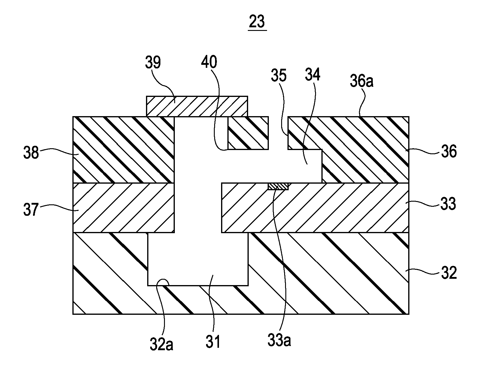
[0127] In Example 2, an ink-jet recording head 23 shown in FIG. 4 was produced as follows. First, on a first substrate 33 having a discharge-energy-generating element 33a shown in FIG. 7, for example, a positive-type resist that was mainly composed of a novolak resin (PMER-P-LA900PM manufacture by Tokyo Ohka Kogyo Co., Ltd.) was applied as a soluble resin layer. The positive-type resist was then pre-baked on a hot plate at 110° C. for six minutes. A pattern exposure of an individual flow path 34 was then performed with a mirror projection aligner (MPA-600FA) manufactured by Canon Inc. Thus, as shown in FIG. 8, an ink flow path pattern 41 was formed with the soluble resin layer at an area where the individual flow path 34 is formed. In this step, the light exposure was 800 mJ / cm2.

[0128] A dip development was performed with a P-7G special developer (3% TMAH (tetramethylammonium hydroxide solution)) to develop the resist, and the first substrate 33 was then rinsed with running pure wa...


PUM


Abstract

A liquid discharge recording head which discharges a liquid includes a substrate on which liquid-discharge-energy-generating elements are provided and which constitutes a part of a flow path for supplying the liquid; and a covering resin layer which is provided on the substrate, which constitutes a part of the flow path, and which includes orifices for discharging the liquid, wherein the covering resin layer is composed of an oxetane resin composition containing an oxetane compound having at least one oxetanyl group in its molecule and a photocationic polymerization initiator as essential components.

Description

CROSS REFERENCES TO RELATED APPLICATIONS [0001] The present application contains subject matter related to Japanese Patent Application JP 2005-229902 filed in the Japanese Patent Office on Aug. 8, 2005, the entire contents of which are incorporated herein by reference. The benefit of priority is not claimed. BACKGROUND OF THE INVENTION [0002] 1. Field of the Invention [0003] The present invention relates to a liquid discharge recording head including highly accurate flow paths that have a low stress and satisfactory chemical resistance and that are formed by patterning with ultraviolet irradiation or the like, and a liquid discharge apparatus including the same. [0004] 2. Description of the Related Art [0005] An example of liquid discharge apparatuses is an ink-jet printer apparatus that discharges, for example, ink as a liquid and that employs an ink-jet recording method (liquid-jet recording method). Such an ink-jet printer apparatus includes an ink-jet recording head for discharg...

Claims


Application Information

Patent Timeline
Patent Type & Authority Applications(United States)
IPC IPC(8): B41J2/045
CPCB41J2/1404B41J2/14145B41J2/1632B41J2/1629B41J2/1631B41J2/1603
Inventor IGARASHI, KOICHIONO, SHOGOTOMITA, MANABUKOHNO, MINORU
Owner SONY CORP
Why Eureka
Try Eureka