Signal transmission apparatus

a transmission apparatus and signal technology, applied in the field of signal transmission apparatus, can solve the problems of high labor cost of wireless base station construction or maintenance, increase in transmission power level and reception signal level, and increase in construction cost of wireless base station or maintenance labor, and achieve the effect of simple configuration

Inactive Publication Date: 2007-08-23
PANASONIC CORP
View PDF6 Cites 22 Cited by
  • Summary
  • Abstract
  • Description
  • Claims
  • Application Information

AI Technical Summary

Benefits of technology

[0029] According to the present invention, it is possible to provide a signal transmission apparatus in which up and down signal levels in a wireless base station and a forward base station can be automatically adjusted to predetermined levels respectively with a simple configuration.

Problems solved by technology

However, when the call zone is narrowed, the number of wireless base stations increases so that the construction cost of the wireless base stations or the labor of maintenance increases.
However, when a wire transmission line such as an optical fiber is exchanged or the forward base station is moved or added so that the length of the transmission line or the number of branches changes, the transmission power level and the up reception signal level have to be adjusted again, and much labor is required therefor.
In addition, the system configuration becomes complicated because a function of detecting abnormality of the forward base station is also provided.
Thus, the transmission line is limited to an optical fiber.
It is therefore difficult to apply the optical micro-cell transmission system to a configuration where a transmission line of a coaxial cable or the like having a limited transmission band is used.

Method used


Image

  • Signal transmission apparatus
  • Signal transmission apparatus
  • Signal transmission apparatus

Examples


first embodiment

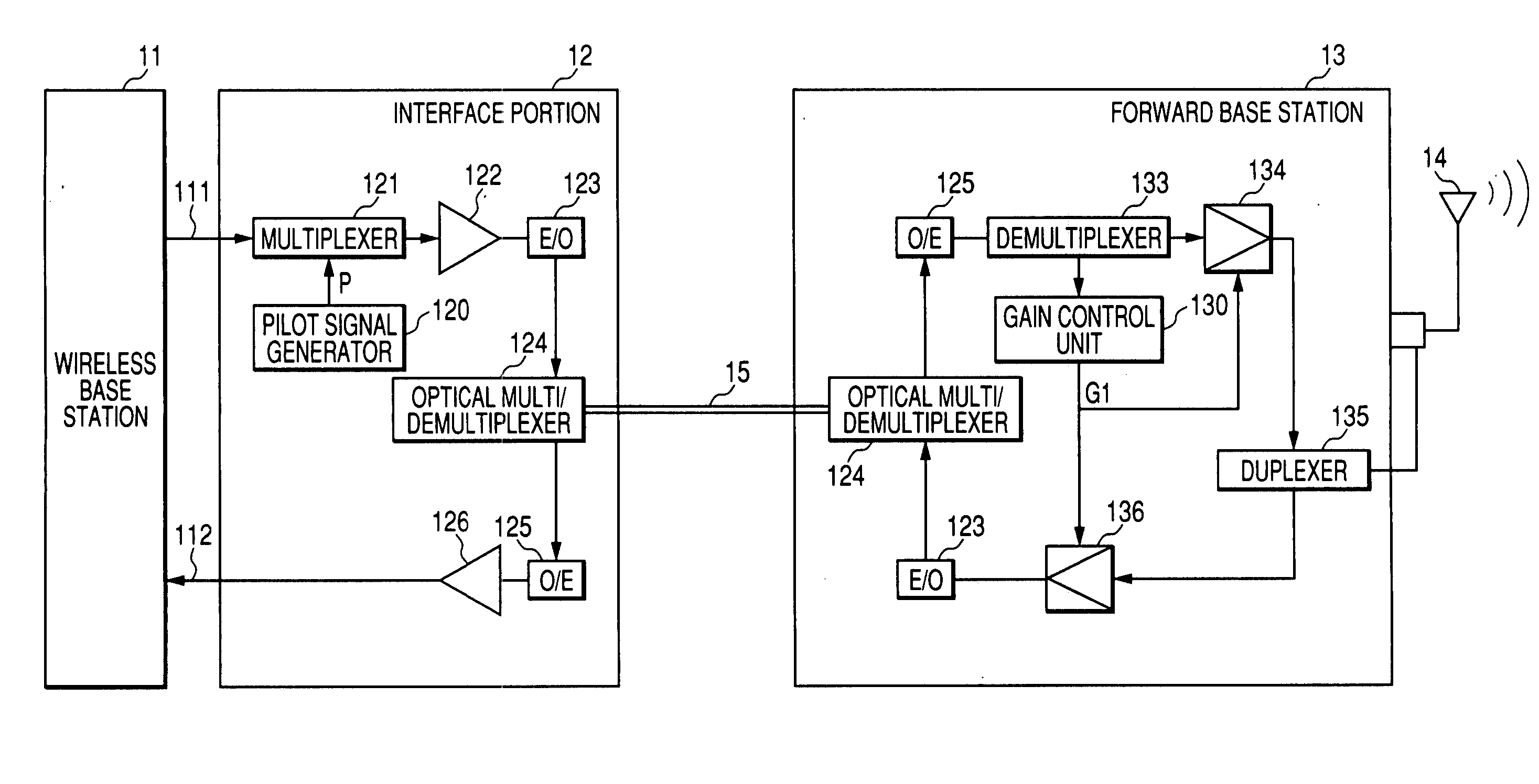
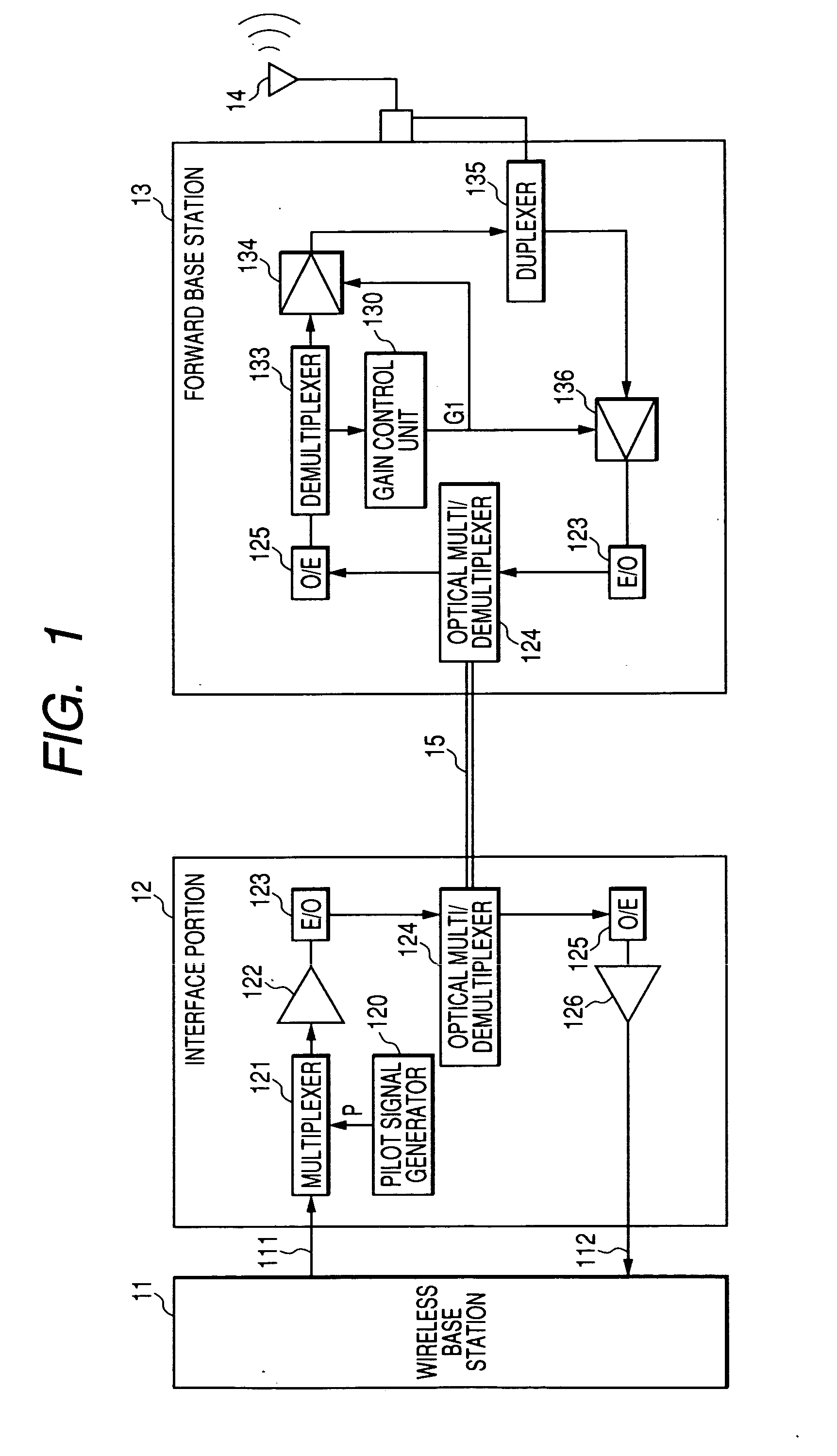
[0065]FIG. 1 is a diagram showing the schematic configuration of a signal transmission apparatus according to a first embodiment of the present invention. In the configuration, an interface portion 12 connected to a wireless base station 11, and a forward base station 13 making wireless communication with mobile communication terminals in a micro-cell covered by the forward base station 13 itself through an antenna 14, are connected through a single optical fiber 15. A plurality of interface portions 12 are typically connected to the wireless base station 11 so as to perform mutual signal transmission with forward base stations installed in a plurality of micro-cells respectively in a call zone assigned to the wireless base station 11 itself. However, the plurality of interface portions 12 are not shown in FIG. 1.

[0066] The interface portion 12 is designed to have a pilot signal generator 120 (equivalent to an example of a pilot signal generating portion) for generating a pilot sig...

second embodiment

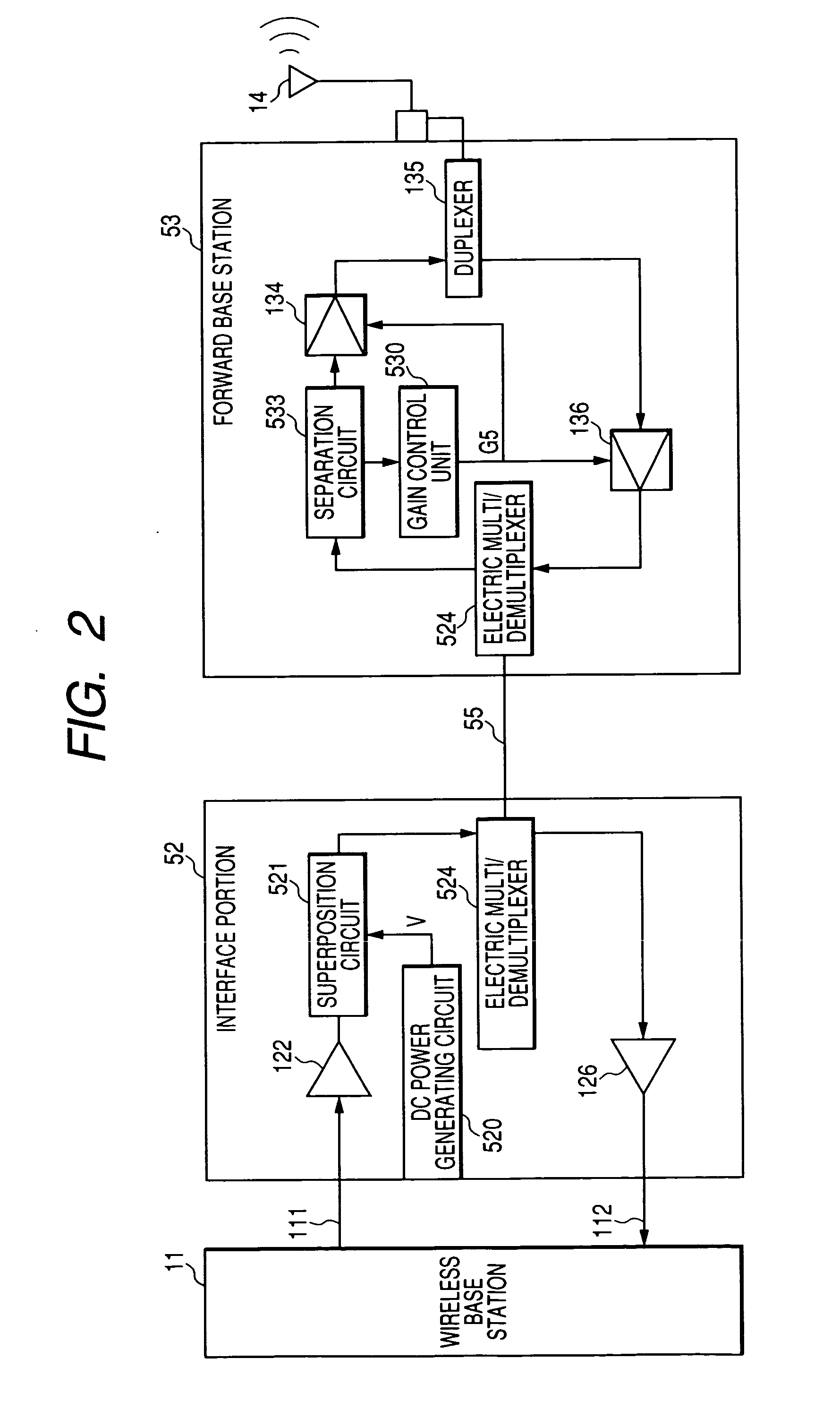
[0075]FIG. 2 is a diagram showing the schematic configuration of a signal transmission apparatus according to a second embodiment of the present invention. In the configuration, an interface portion 52 connected to a wireless base station 11 and a forward base station 53 are connected through a single-wire metallic cable 55 such as a coaxial cable or the like.

[0076] The interface portion 52 is designed to have a down signal amplifier 122 for amplifying a down transmission signal 111 input from the wireless base station 11 with a predetermined constant gain, a DC power generating circuit 520 (equivalent to an example of a DC power generation portion) for generating DC power V of a predetermined level, a superposition circuit 521 for superposing the DC power V on the amplified down transmission signal, an electric multi / demultiplexer 524 for frequency-multi / demultiplexing a down transmission signal and an up reception signal transmitted through the metallic cable 55, and an up signal...

third embodiment

[0085]FIG. 3 is a diagram showing the schematic configuration of a signal transmission apparatus according to a third embodiment of the present invention. In the configuration, an interface portion 32 connected to a wireless base station 11 and a forward base station 33 are connected through a two-wire metallic cable such as a twisted pair cable or the like constituted by a down signal transmission line 35 and an up signal transmission line 36.

[0086] The interface portion 32 is designed to have a down signal amplifier 122 for amplifying a down transmission signal 111 input from the wireless base station 11 with a predetermined constant gain, an up signal amplifier 126 for amplifying an up reception signal transmitted from the forward base station 33 through the up signal transmission line 36 with a constant gain, a pilot signal generator 120 (equivalent to an example of a pilot signal generation portion) for generating a pilot signal P of a predetermined level, and a multiplexer 32...


PUM


Abstract

Up and down signal levels in a wireless base station and a forward base station can be automatically adjusted into predetermined levels respectively with a simple configuration. In an interface portion 12, a pilot signal P of a predetermined level is generated by a pilot signal generator 120, and multiplexed with a down transmission signal 111 from a wireless base station 11 by a multiplexer 121. The multiplexed signal is amplified with a constant gain by a down signal amplifier 122, then converted into a down optical signal by an electro-optic converter 123, wavelength-multiplexed by an optical multi/demultiplexer 124, sent out to an optical fiber 15, and transmitted to a forward base station 13. In the forward base station 13, the down optical signal wavelength-demultiplexed by an optical multi/demultiplexer 124 is converted into a down electric signal by an opto-electric converter 125, and the pilot signal P is demultiplexed by a demultiplexer 133. A gain control unit 130 detects an absolute level of the pilot signal P, and outputs a gain control signal G1 to set the level value at a predetermined rated value. A down signal gain variable amplifier 134 and an up signal gain variable amplifier 136 amplify the down transmission signal and the up reception signal respectively with a gain controlled by the gain control signal G1.

Description

TECHNICAL FIELD [0001] The present invention relates to a signal transmission apparatus for transmitting signals between a wireless base station and a forward base station connected to this wireless base station through a wire transmission line in a mobile communication system. BACKGROUND ART [0002] In a mobile communication system, a service area is divided into call zones, and a wireless base station is installed in each call zone. Each subscriber's wireless terminal (mobile communication terminal) such as each cellular phone or the like makes communication with this wireless base station by wireless. The wireless base station does not have only a radio transmitter-receiver but has a configuration in which functions such as processing in a baseband, interface with an exchange network, processing for time division or space division, call switching, etc. are aggregated. It is desired to make each call zone as narrow as possible from the point of view of power saving of each mobile c...

Claims


Application Information

Patent Timeline
Patent Type & Authority Applications(United States)
IPC IPC(8): H04Q7/20H04M1/00H04B1/38
CPCH04B10/25758H04J14/0221H04J14/02
Inventor ODA, KATSUYATOHGOH, HITOMAROSATO, YOSHIYASUASANO, HIROAKI
Owner PANASONIC CORP
Why Eureka
Try Eureka