

Nanocomposites With Controlled Electrical Properties
a technology of electrical properties and nanocomposites, applied in the direction of inorganic insulators, inhomogeneous insulation materials, transportation and packaging, etc., can solve the problems of additives having negative effects on electrical properties, high electric stresses, and harmful electric equipment, so as to improve dielectric properties, resistivity, permittivity and/or electrical breakdown strength.
- Summary
- Abstract
- Description
- Claims
- Application Information
AI Technical Summary
Benefits of technology
Problems solved by technology
Method used
Image


Examples
example 1
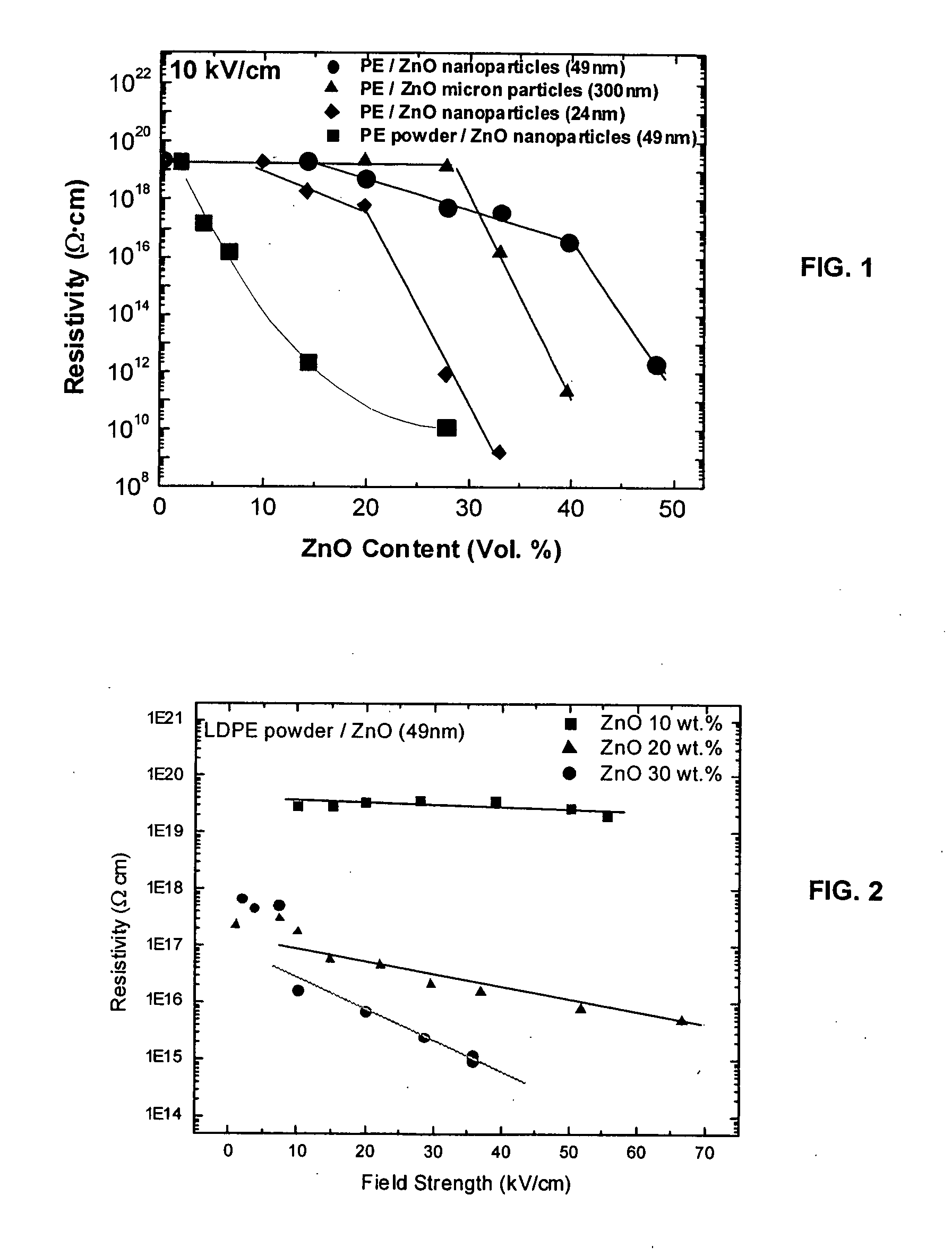
Heterogenous Distribution of ZnO Nanoparticles in LDPE Matrix
[0039] Experimental: ZnO nanoparticles were donated by Nanophase Technologies Corporation, and the average particle size was determined to be approximately 50 nm from TEM observation. For uniform distribution of filler particles, the nanoparticles were melt-mixed with low density polyethylene (LDPE; DOW 6811) pellets using a torque rheometer (Haake batch mixer system 90). The resulting composite was then examined with field-emission scanning electron microscope (FESEM, JEOL JSM-6335F), and fillers were observed to be well dispersed and distributed uniformly in the polymer matrix. Non-uniform distribution of the filler in the matrix was achieved by ball milling the nanoparticles with micron-size LDPE powders obtained from Ultra Chemical Inc. The mixture of particles was ball milled at room temperature for 24 hours so that ZnO nanoparticles were embedded in the soft surface of the LDPE particles. Neither the LDPE powders no...
example 2
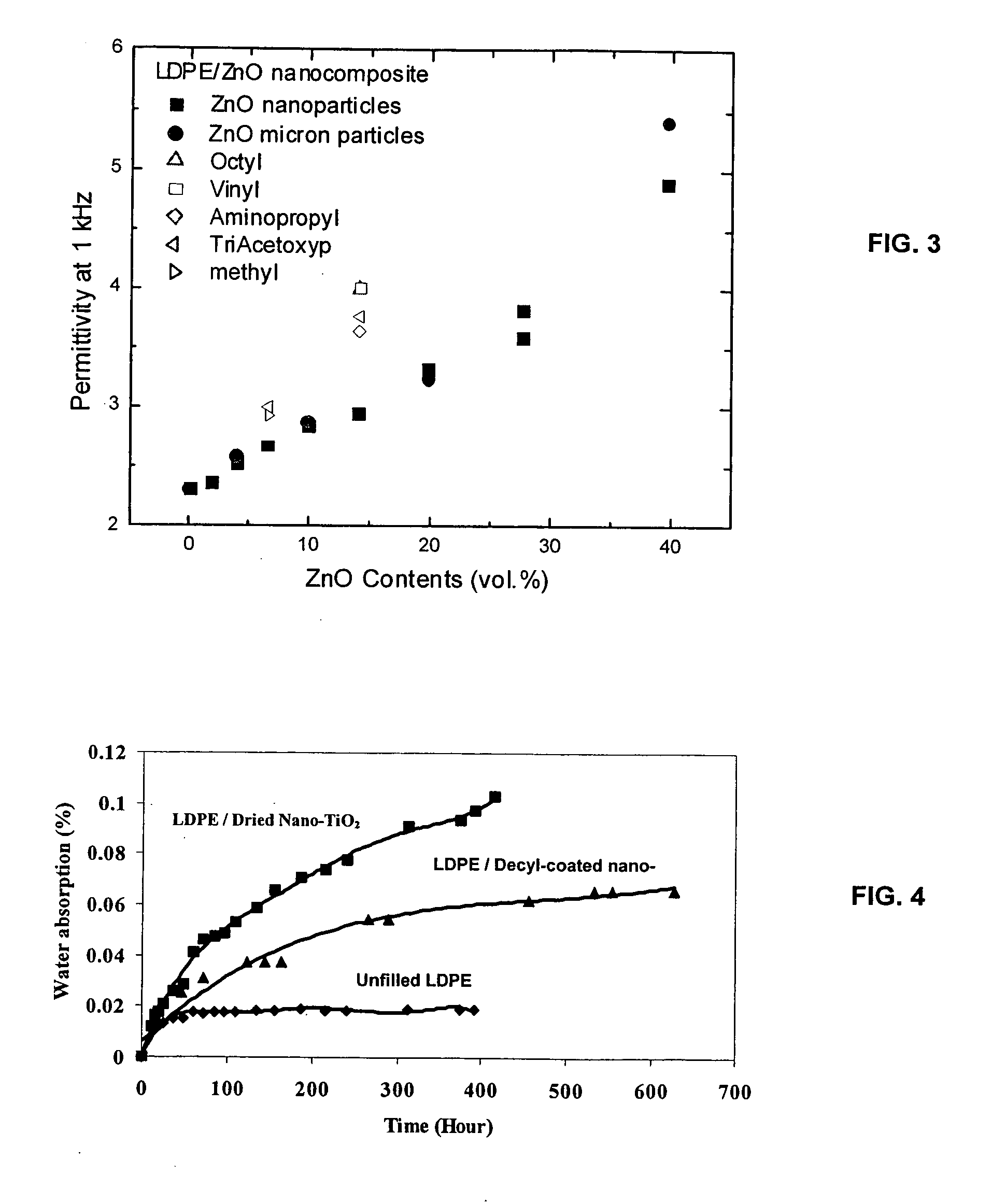
Dielectric Properties of ZnO / LDPE Nanocomposites
[0045] Experimental: ZnO / LDPE nanocomposites were produced by melt mixing commercial grade DOW 6811 LDPE and 49 nm ZnO nanoparticles in a Haake batch mixer. ZnO nanoparticles were obtained from Nanophase Technologies Corporation. To avoid any thermal degradation of the polymer matrix, the mixing time was set to 10 to 13 minutes at 200° C. The specimen was then hot pressed into a disc shape with a diameter of 6.35 cm for the measurements of permittivity.
[0046] In order to realize the property changes resulting from the addition of nanoscale fillers, they must be dispersed well within the matrix. To observe dispersion, the composites were cooled below their glass transition temperature and fractured. The fracture surface was examined with field emission scanning electron microscope (JEOL JSM-6335F) operated at 5 kV. SEM images showed that the particles were dispersed quite well.
[0047] The permittivity of the nanocomposite was measured...
example 3
Breakdown Strength of TiO2 / LDPE Nanocomposites
[0053] Experimental Approach: The matrix used in this study was low-density polyethylene (LDPE) DOW 6811. The basic characteristics of LDPE 6811 are: density 0.922 g / cc and melt index 1.2 g / 10 min. Both micron-scale (1-2 μm) from Aldrich and nano-size (23 nm average diameter) TiO2 from Nanophase Technologies Corporation were used as fillers. Five weight percent TiO2 particles were mixed into LDPE at 130° C. in a melt mixer. Films with a thickness of 10-40 μm were obtained using compression molding at 160° C. under a pressure of about 14 MPa. The temperature of the film was decreased to 50-60° C. slowly in the mold under pressure before it was removed from the mold and air-cooled to room temperature. Each sample was then kept in a desiccator for at least one day before the breakdown strength was measured in case residual internal stress influences the experimental results. Unfilled pure LDPE went through exactly the same process in order...
PUM
| Property | Measurement | Unit |
|---|---|---|
| Percent by volume | aaaaa | aaaaa |
| Percent by volume | aaaaa | aaaaa |
| Percent by volume | aaaaa | aaaaa |
Abstract
Description
Claims
Application Information