Constant current zero-voltage switching induction heater driver for variable spray injection

a technology of variable spray injection and heater, which is applied in the direction of fuel injectors, machines/engines, electric control, etc., can solve the problems of high hydrocarbon emissions of conventional spark ignition internal combustion engines, poor fuel ignition and combustibility, and excessive crank tim

Active Publication Date: 2007-08-30
VITESCO TECH USA LLC
View PDF9 Cites 58 Cited by
  • Summary
  • Abstract
  • Description
  • Claims
  • Application Information

AI Technical Summary

Benefits of technology

[0028]The method may further comprising the steps of, in a first gate diode, preventing current flow from the second node to the gate of the first oscillator switch, and, in a second gate diode, preventing current flow from the first node to the gate of the second oscillator switch. In that case, the method may further include the steps of providing a first gate resistor connecting the gate of the first oscillator switch and the first gate diode to a gate supply voltage; and providing a second gate resistor connecting the gate of the second oscillator switch and the second gate diode to the gate supply voltage.

Problems solved by technology

During cold temperature engine start, the conventional spark ignition internal combustion engine is characterized by high hydrocarbon emissions and poor fuel ignition and combustibility.
Unless the engine is already at a high temperature after stop and hot-soak, the crank time may be excessive, or the engine may not start at all.
Such systems are expensive and redundant.
Both those solutions require electrical connections penetrating through the injector wall into the fuel passage, leading to an increased risk of fuel leakage.
Hard-switching of power results in the negative consequences of switching noise, and high amplitude current pulses at resonant frequency from the voltage supply, or harmonics thereof.
Also, hard switching dissipates power during the linear turn-on and turn-off period when the switching device is neither fully conducting nor fully insulating.
The higher the frequency of a hard-switched circuit, the greater the switching losses.
Heated fuel injectors have required additional conductors for driving the heating elements in the injectors, Those additional conductors have complicated the connectors and harnesses, and have increased expense and potential failure points in the wiring system.

Method used


Image

  • Constant current zero-voltage switching induction heater driver for variable spray injection
  • Constant current zero-voltage switching induction heater driver for variable spray injection
  • Constant current zero-voltage switching induction heater driver for variable spray injection

Examples


embodiment 300

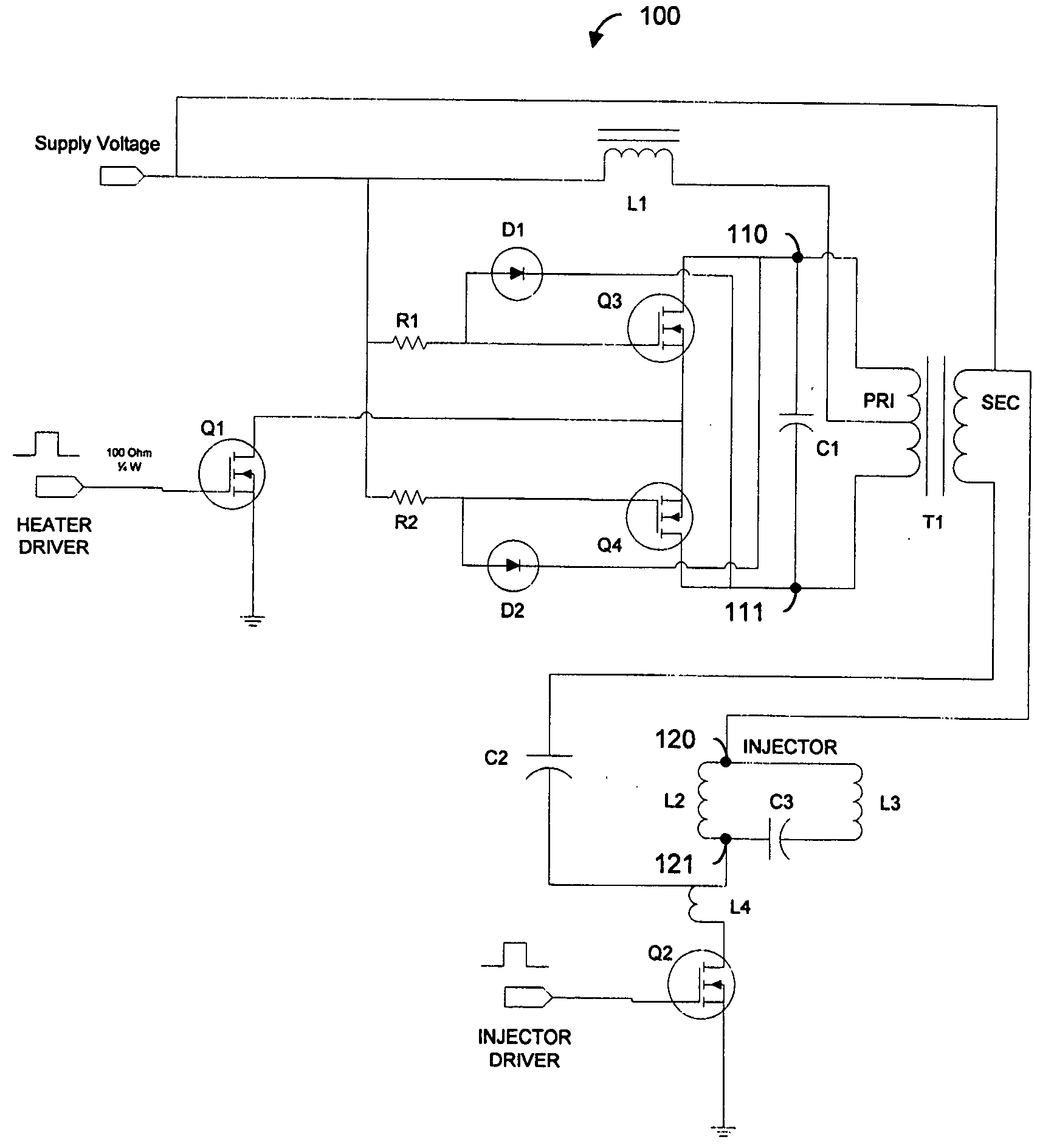
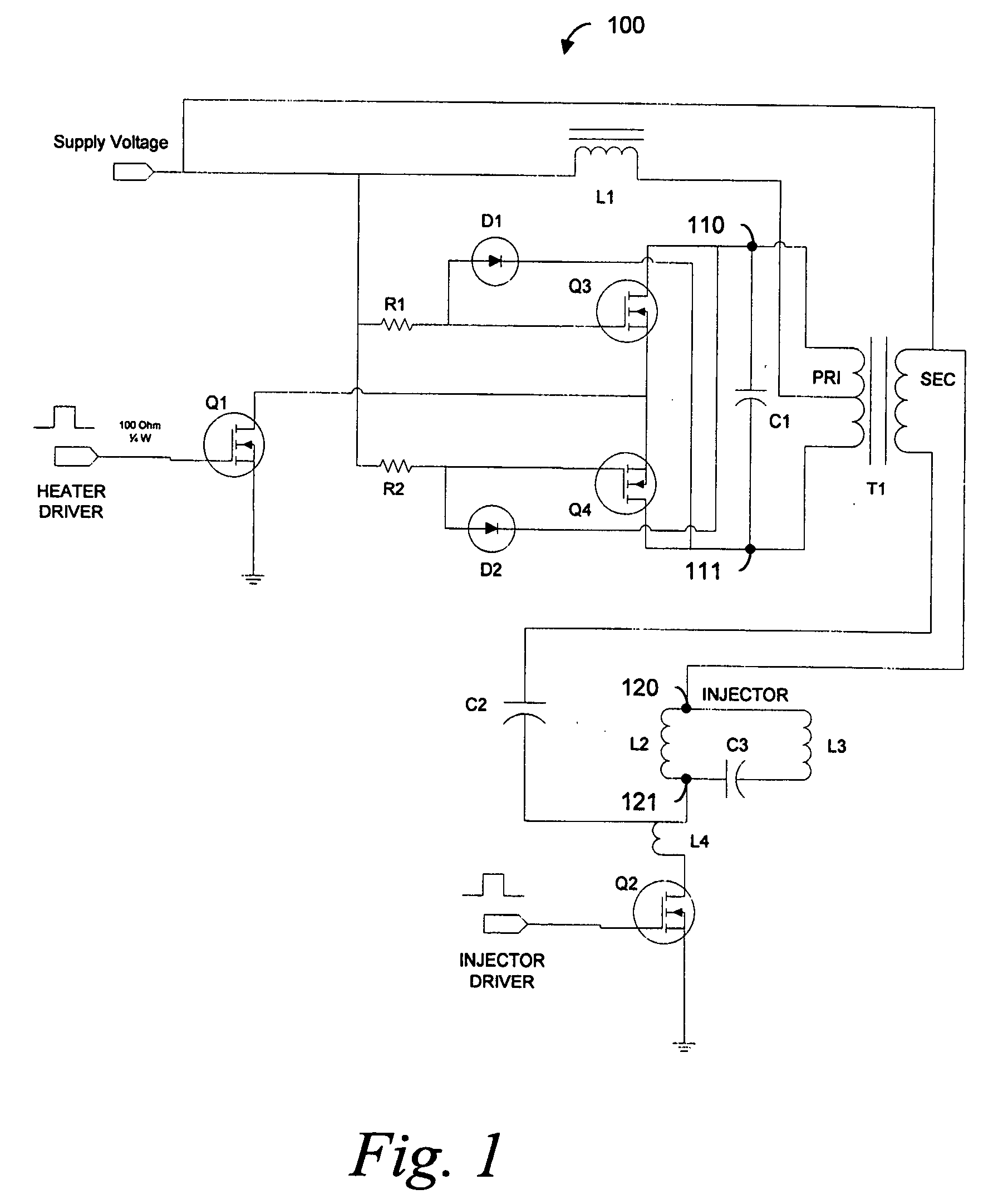
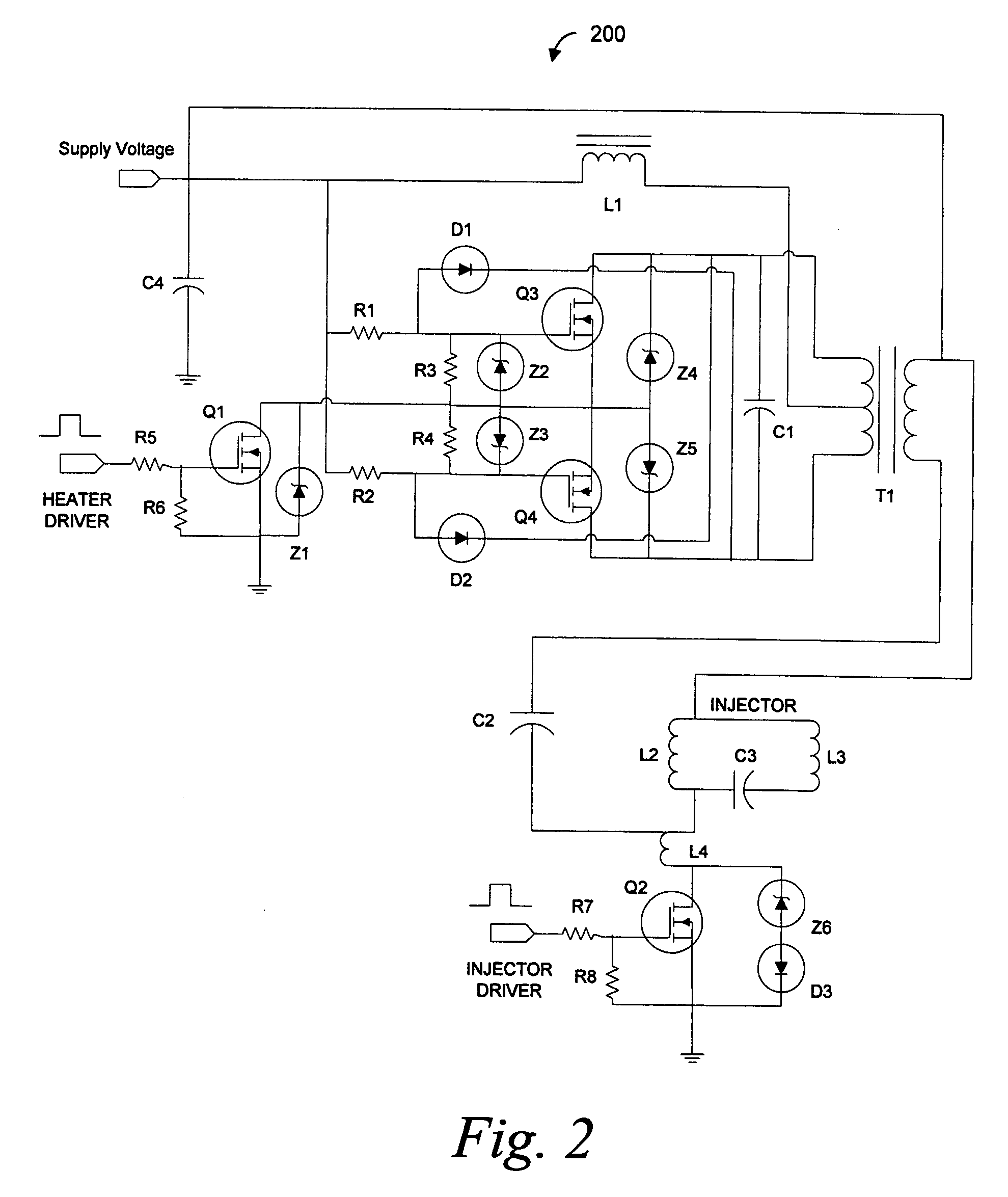
[0062]FIG. 3 depicts an embodiment 300 of the heater driver and injector driver circuit of FIG. 2. Specific component values and specifications are shown in FIG. 3 to illustrate a working prototype. Those values and specifications are merely exemplary and are not intended to limit the scope of the invention.

[0063]The heater driver transformer T1 and the current source inductor L1 may be combined into a hybrid component 400, shown in FIG. 4a. In such a hybrid component, the current source inductor 410 directly taps the high side of the secondary winding 420 of the heater driver transformer for the constant input current.

[0064]The heater driver / injector driver arrangement of the invention may include electromechanical valve actuators other than solenoid actuators. For example, as illustrated in FIG. 4b, a piezoelectric actuator, shown as capacitor 470, may be substituted for the solenoid L2 of FIG. 1. In that case, the piezoelectric actuator 470, together with an inductor 460 in serie...

embodiment 500

[0065]FIG. 5 depicts an alternative embodiment 500 which uses the combined low impedance point, of ground and supply voltage, as the return path for the high frequency alternating current back to T1. That embodiment includes an additional MOSFET switch Q5, enabled when Q1 is enabled, and a high pass filter in the form of an AC bypass capacitor C5 to shunt the high frequency current to ground when Q2 is not turned ‘on.’ The primary disadvantage to that alternative embodiment is that the induction heater must be turned off in a duration window including and prior to the injection driver, Q2, turn-off, otherwise the injection valve closing will be different with the AC bypass capacitor C5 shunting across Q2. Specific component values are shown in FIG. 5 and reflect a working prototype of this embodiment.

[0066]FIG. 6 depicts a gate voltage 610 of Q3 at 5 volts per division, the drain-to-drain voltage 620 across Q3 and Q4 at 25 volts per division, which is the tank voltage, and the heati...


PUM


Abstract

An electronic high frequency induction heater driver, for a variable spray fuel injection system, uses a zero-voltage switching oscillator that is impedance coupled to an imbedded multiple function signal separator and integrated with a conventionally implemented electronic fuel injector driver. The induction heater driver, upon receipt of a turn-on signal, multiplies a supply voltage through a self-oscillating series resonance, and couples the high frequency energy to a high pass filter such that the useful energy is utilized in an appropriate loss component so that fuel inside a fuel component is heated to a desired temperature.

Description

CROSS REFERENCE TO RELATED APPLICATIONS[0001]This application claims the benefit of priority from U.S. Provisional Patent Application Ser. No. 60 / 777,084 entitled “Constant Current Zero-Voltage Switching Induction Heater Driver for Variable Spray Injection,” filed on Feb. 27, 2006, the contents of which are hereby incorporated by reference herein in their entirety.FIELD OF THE INVENTION[0002]The present invention relates generally to heated tip fuel injectors, and more particularly, to a method and apparatus for controlling and driving an induction-heated fuel injector.BACKGROUND OF THE INVENTION[0003]There is a continued need for improving the emissions quality of internal combustion engines. At the same time, there is pressure to minimize engine crank times and time from key-on to drive-away, while maintaining maximum fuel economy. Those pressures apply to engines fueled with alternative fuels such as ethanol as well as to those fueled with gasoline.[0004]During cold temperature e...

Claims


Application Information

Patent Timeline
Patent Type & Authority Applications(United States)
IPC IPC(8): F02D1/06F02M63/00
CPCF02M53/06F02D41/20
Inventor CZIMMEK, PERRY ROBERT
Owner VITESCO TECH USA LLC
Why Eureka
Try Eureka