Asymmetric directional coupler having a reduced drive voltage

a technology drive voltage, which is applied in the field of asymmetric directional coupler having a reduced drive voltage, can solve the problems of difficult structure to manufacture successfully, difficult to manufacture directional couplers for switching, and difficult to manufacture successfully directional couplers. achieve the effect of reducing the operating voltag

Active Publication Date: 2007-08-30
LUMENTUM OPERATIONS LLC
View PDF61 Cites 15 Cited by
  • Summary
  • Abstract
  • Description
  • Claims
  • Application Information

AI Technical Summary

Benefits of technology

[0014]The present invention has found that by careful selection of an asymmetric directional coupler geometry, the transfer function of the device can be shifted so that it has an operating point between maximum and minimum transmission. Signal electrodes driven in push pull configuration advantageously use this operating point to achieve significant reduction in operating voltages for switching to maximum or minimum transmission. By operating point it is understood in the present application to refer to the percentage of coupling which occurs at zero applied volts in the transfer function of the device.

Problems solved by technology

Directional couplers have been difficult to manufacture successfully for switching and related applications, in part because the manufacturing tolerances to achieve the proper coupling length and precise symmetry required have been commercially challenging, and in part because the wavelength range of the coupler has been narrower than necessary for the application.
If full coupling does not occur from one waveguide to the other because the coupling length is not correct, excess optical loss is introduced and / or full extinction cannot be achieved, thus making the coupler unsuitable for many applications.
However, it is a very difficult structure to manufacture successfully.
An error in the fabricated coupling length of the directional coupler will result in incomplete coupling that cannot be corrected by voltage.
This means as discussed above, that full extinction would not be possible, and the dynamic range of the device would be limited.
One problem with prior art high-speed variable optical attenuators fabricated in lithium niobate is the large voltage that must be applied to the device.
If there is variability in the 2× bias drift multiplier, then even 40V of available drive voltage may be insufficient.

Method used


Image

  • Asymmetric directional coupler having a reduced drive voltage
  • Asymmetric directional coupler having a reduced drive voltage
  • Asymmetric directional coupler having a reduced drive voltage

Examples


Embodiment Construction

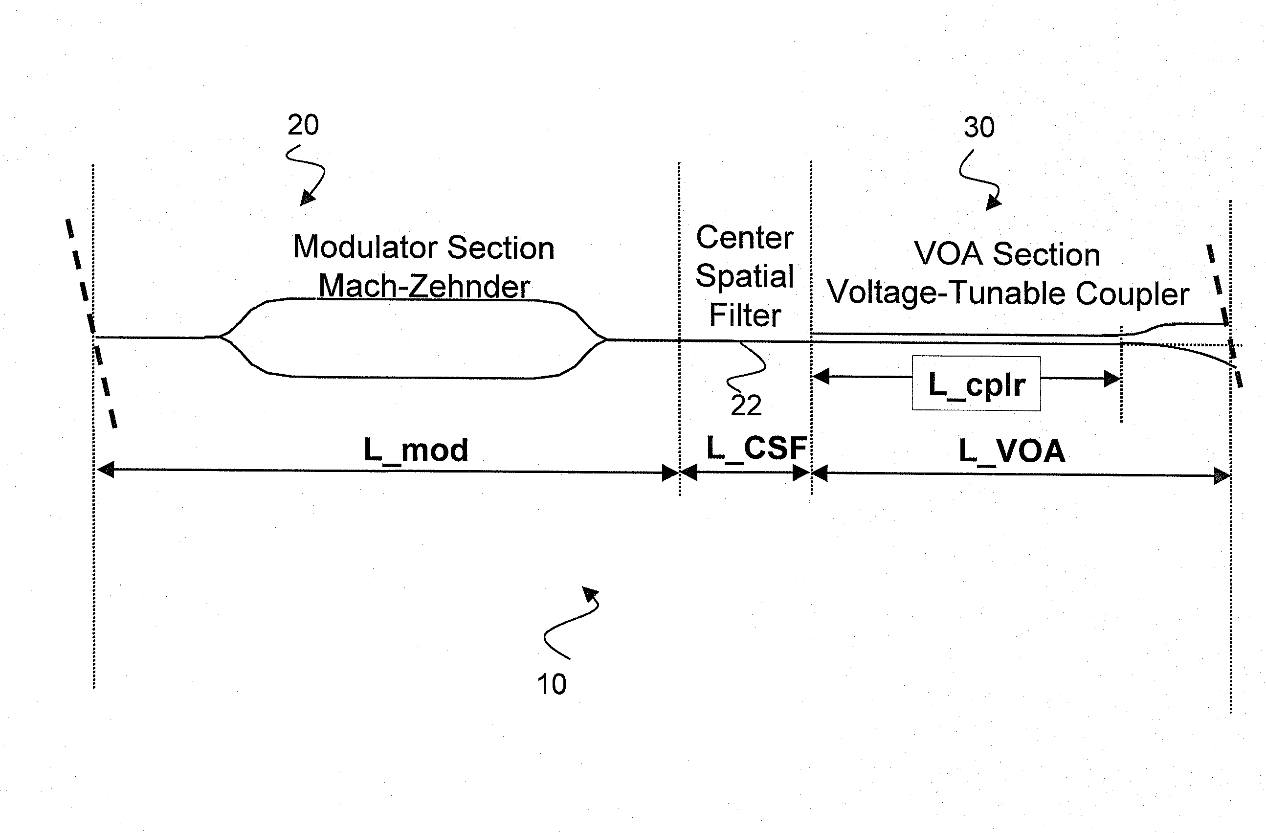
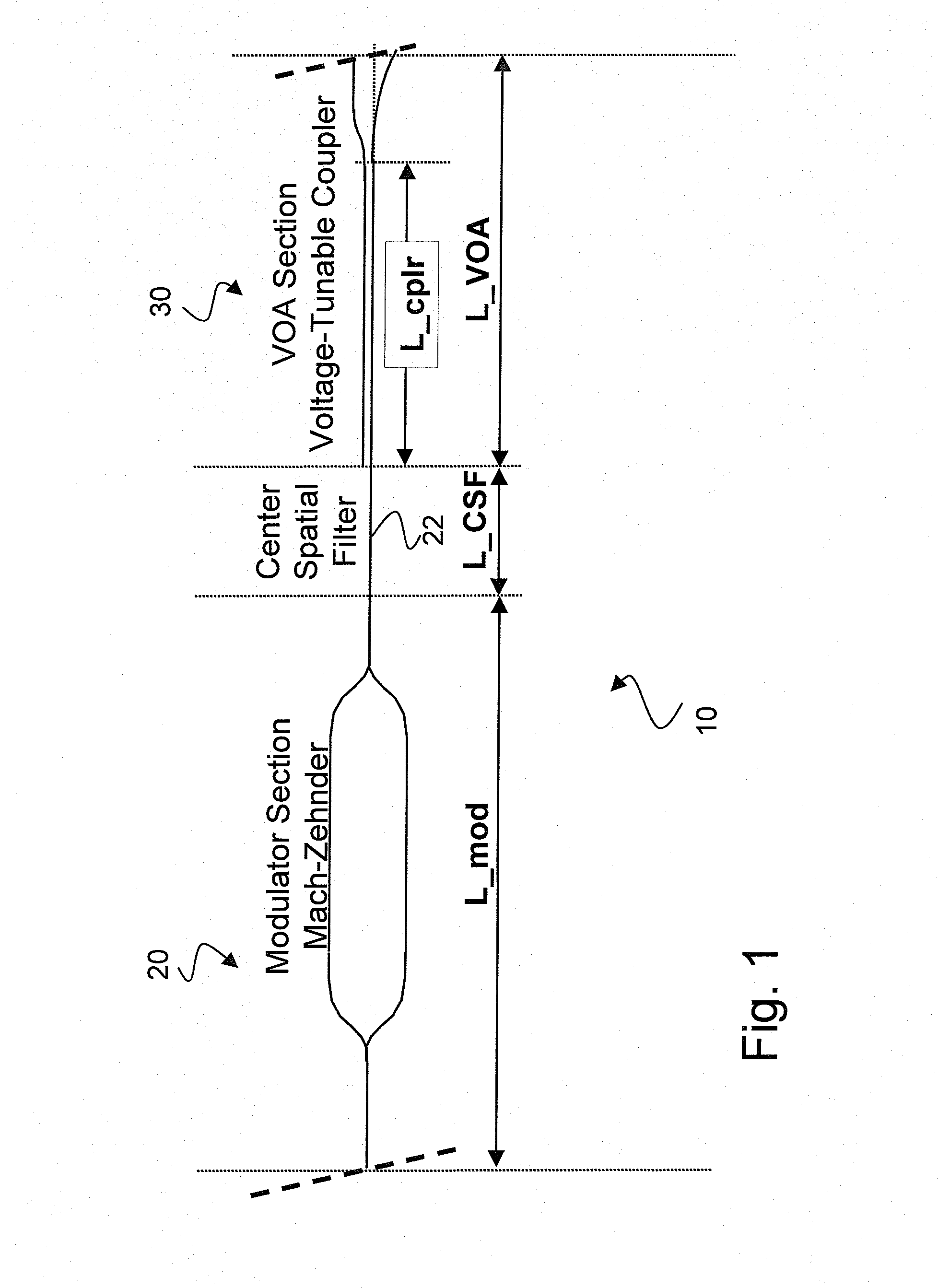
[0047]FIG. 1 shows the waveguide layout for a modulator 10 with a data modulator 20 followed by a directional coupler VOA stage 30. The data modulator 20 is a conventional Mach-Zehnder modulator known in the art. For example, see U.S. Pat. No. 6,845,183 herein incorporated by reference. The modulator is a digital modulator suitable for data rates ranging from 10-43 Gbits or higher. Accordingly, a VOA for this application typically has an electro-optic bandwidth of at least 100 MHz, though, a bandwidth of 1-10 MHz may be adequate for many applications. The straight waveguide section 22 in between the Mach-Zehnder 20 and VOA 30 provides optical isolation of the two stages.

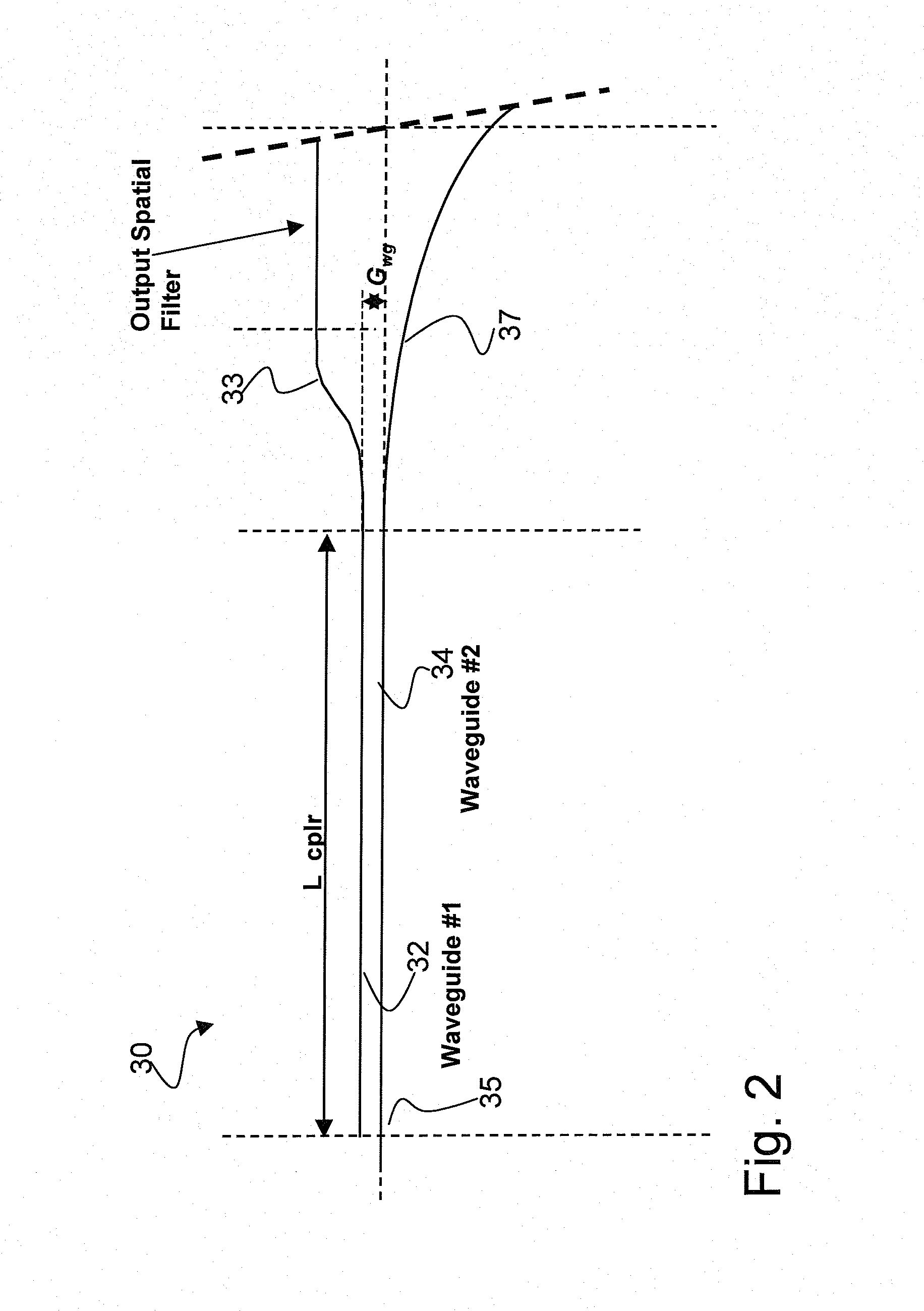
[0048]FIG. 2 shows a close-up of the VOA, which consists of a voltage controlled directional coupler 30. The coupler 30 comprises an electro-optic substrate 40, preferably lithium niobate, into which titanium is diffused to form waveguides 32,34. The two waveguides 32,34 are disposed in close proximity, such that pow...


PUM

PropertyMeasurementUnit
drive voltageaaaaaaaaaa
SOL drive voltageaaaaaaaaaa

Abstract

The invention relates to an electro-optic directional coupler suitable for use as a variable optical attenuator at reduced voltages compared to those known in the prior art. The present invention has found that by careful selection of an asymmetric directional coupler geometry, the transfer function of the device can be shifted so that it has an operating point between maximum and minimum transmission. Signal electrodes driven in push pull configuration advantageously use this operating point to achieve significant reduction in operating voltages for switching to maximum or minimum transmission. Asymmetry is created in the directional coupler by forming the waveguides to have different propagation constants by a difference in waveguide width, depth, index of refraction or index profile. Asymmetry can alternatively be created by causing mechanical stress in the waveguides through the placement, number, or dimensions of the electrodes, or through asymmetric dielectric structures between the waveguides and the electrodes.

Description

CROSS-REFERENCE TO RELATED APPLICATIONS[0001]This application claims priority from U.S. provisional application No. 60 / 777,091 filed Feb. 27, 2006, herein incorporated by reference for all purposes.MICROFICHE APPENDIX[0002]Not Applicable.TECHNICAL FIELD[0003]The present application relates to electro-optic directional couplers, particularly an asymmetric directional coupler having a reduced drive voltage.BACKGROUND OF THE INVENTION[0004]Directional couplers comprise two waveguides formed in electro-optic material such as lithium niobate, lithium tantalate or gallium arsenide for example, disposed in close proximity over a coupling length selected to enable evanescent coupling of 100% of the transmitted optical power from one waveguide to the other. An electric field created by a voltage applied through one or both waveguides alters the propagation constant of the waveguide due to the electro-optic effect of the substrate, resulting in a change in the percentage of coupling. Directio...

Claims


Application Information

Patent Timeline
Patent Type & Authority Applications(United States)
IPC IPC(8): G02F1/295G02B6/42G02B6/26
CPCE21B11/005G02B6/122G02F2203/48G02F1/3132G02F2201/14G02B2006/1204
Inventor KISSA, KARLGLASSNER, DAVID
Owner LUMENTUM OPERATIONS LLC
Why Eureka
Try Eureka