

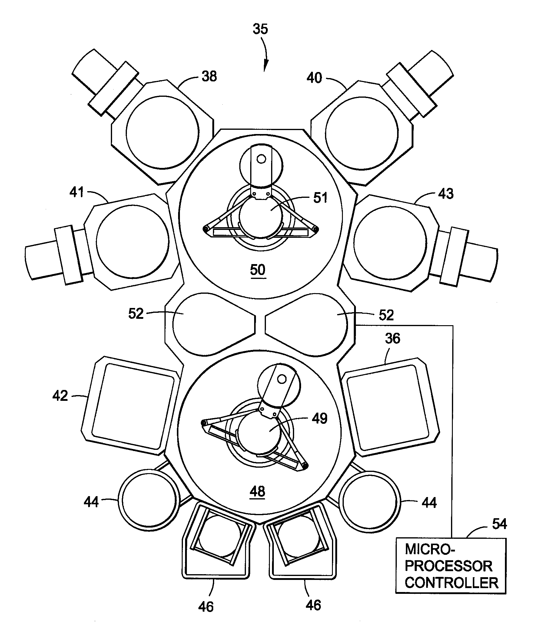
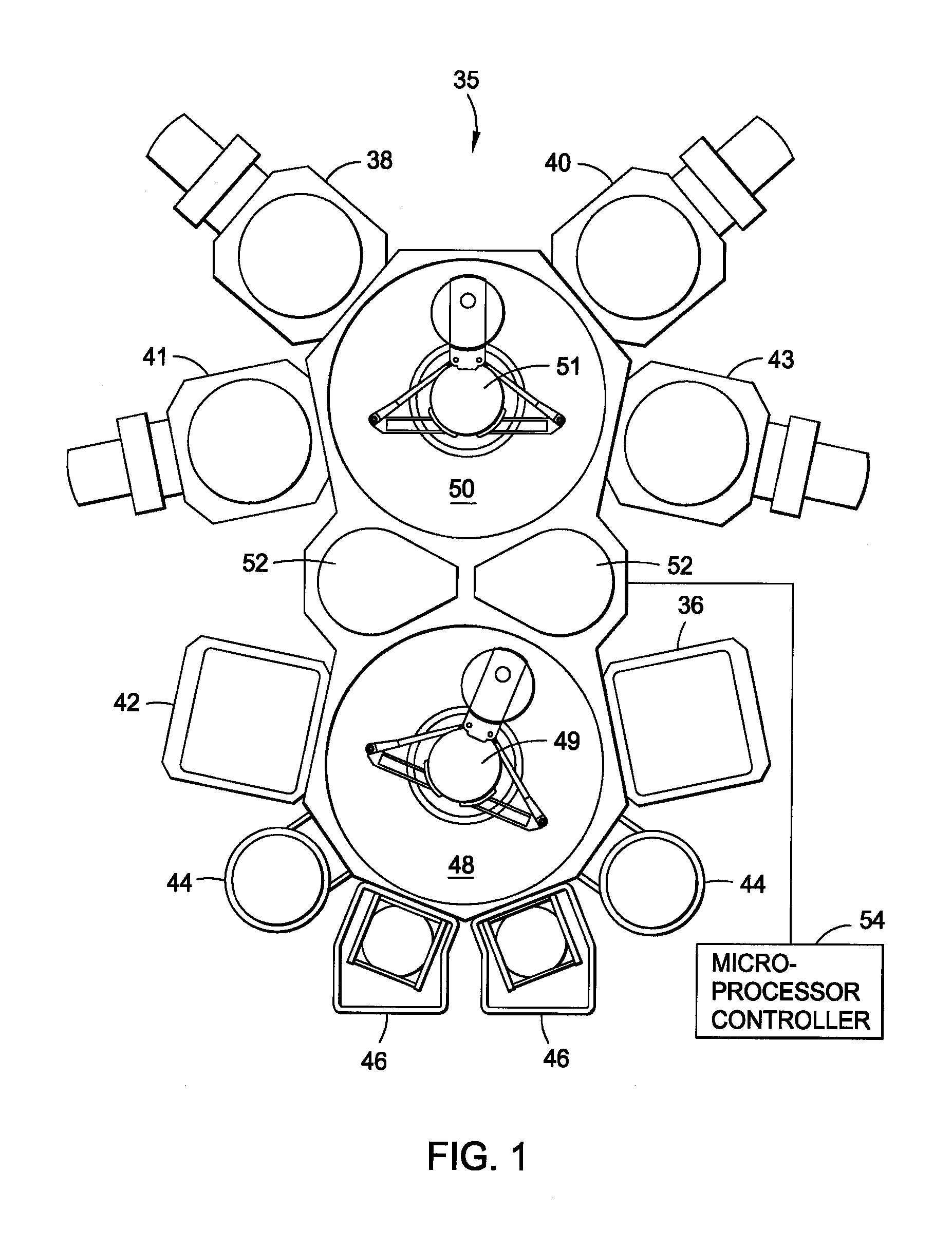
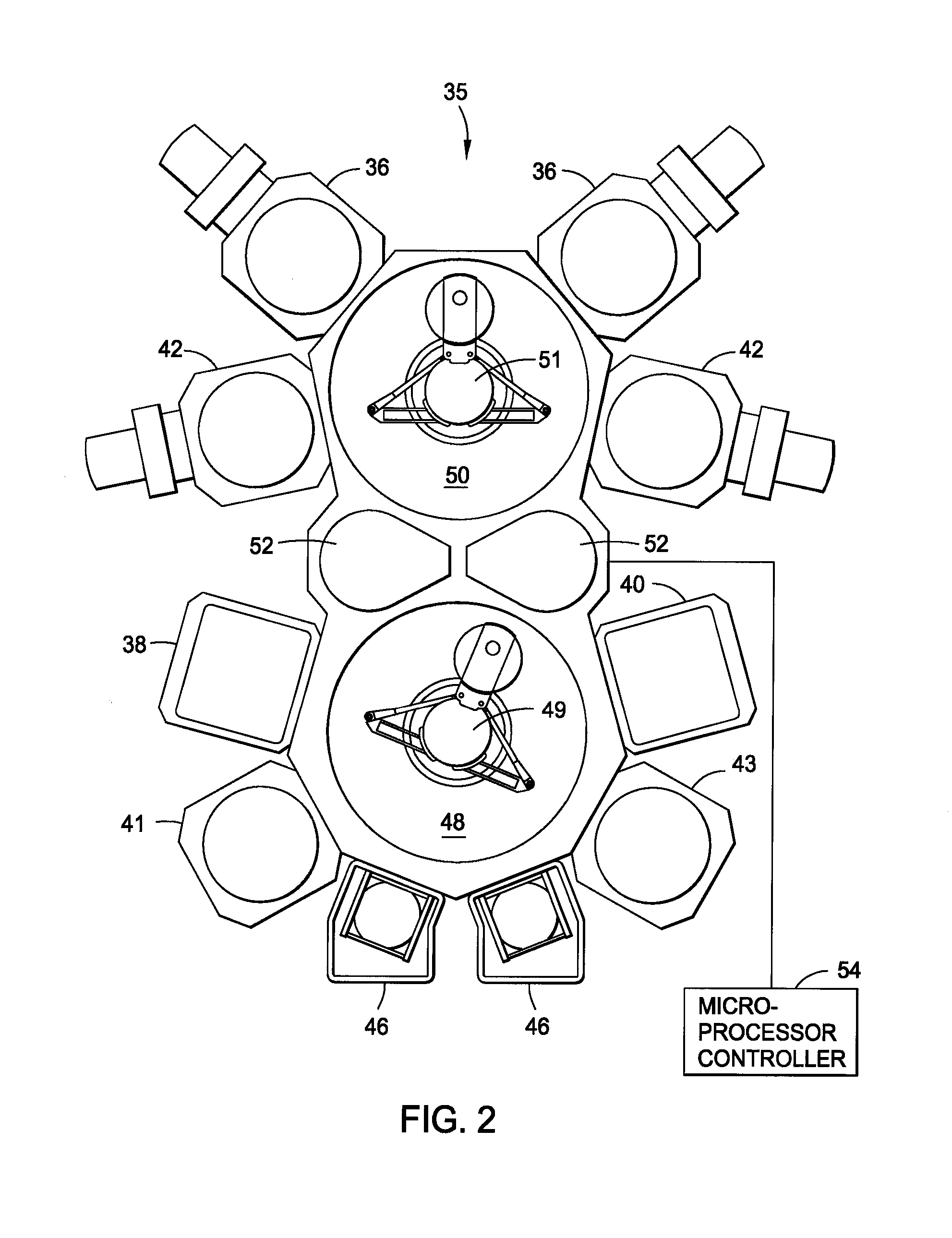
Process for forming cobalt-containing materials
a cobalt-containing material and process technology, applied in the field of semiconductor fabrication, can solve the problems of cobalt agglomeration, difficult to integrate cobalt silicide processes into conventional manufacturing equipment, and reduce the reliability of the overall circui
- Summary
- Abstract
- Description
- Claims
- Application Information
AI Technical Summary
Benefits of technology
Problems solved by technology
Method used
Image

Examples
example 1
[0271] In one example, a cobalt silicide material may be deposited by a thermal CVD process. Purge gas may be flowed through different portions of the deposition chamber. At least one purge gas may be flowed throughout the deposition chamber, such as a bottom purge flowing a purge gas across the bottom the deposition chamber and an edge purge flowing another purge gas across the edge ring. For example, a bottom purge may flow argon having a flow rate of about 1,000 sccm across the bottom the deposition chamber and an edge purge may flow argon having a flow rate of about 100 sccm across the edge ring.
[0272] The substrate may be heated to a temperature within a range from about 350° C. to about 550° C. and the ampoule containing the cobalt precursor may be heated to a temperature of about 30° C. The substrate may be exposed to a deposition gas containing a cobalt precursor, a silicon precursor, hydrogen, and a carrier gas. The cobalt precursor may be a cobalt...
example 2
Metallic Cobalt Material
[0278] In another example, a metallic cobalt material may be deposited by a thermal CVD process. Purge gas may be flowed through different portions of the deposition chamber. At least one purge gas may be flowed throughout the deposition chamber, such as a bottom purge flowing a purge gas across the bottom the deposition chamber and an edge purge flowing another purge gas across the edge ring. For example, a bottom purge may flow argon having a flow rate of about 1,000 sccm across the bottom the deposition chamber and an edge purge may flow argon having a flow rate of about 100 sccm across the edge ring.
[0279] The substrate may be heated to a temperature within a range from about 350° C. to about 550° C. and the ampoule containing the cobalt precursor may be heated to a temperature of about 30° C. The substrate may be exposed to a deposition gas containing a cobalt precursor, hydrogen, and a carrier gas. The cobalt precursor may be a cobalt carbonyl compoun...
PUM
| Property | Measurement | Unit |
|---|---|---|
| Temperature | aaaaa | aaaaa |
| Temperature | aaaaa | aaaaa |
| Temperature | aaaaa | aaaaa |
Abstract
Description
Claims
Application Information