Directly modulated or externally modulated laser optical transmission system with feed forward noise cancellation

a laser optical transmission system and laser technology, applied in electromagnetic transmission, transmission, electrical equipment, etc., can solve the problems of affecting multi-channel video transmission, so as to reduce the phase noise components produced by lasers, reduce the phase noise in transmission, and minimize the effect of phase nois

Inactive Publication Date: 2007-09-06
EMCORE INC
View PDF73 Cites 27 Cited by
  • Summary
  • Abstract
  • Description
  • Claims
  • Application Information

AI Technical Summary

Benefits of technology

[0021]In another aspect, the present invention further provides a low-cost direct modulation technique, preferably including a circuit for controlling an optical phase modulator reducing the phase noise components produced by a laser.
[0022]In another aspect of the invention, there is provided a noise cancellation circuit for reducing phase noise in the transmission of analog signals that splits an output optical signal from the semiconductor laser into two paths, one to a phase modulator and the other to a frequency discriminator. The phase modulation cancellation signal is adjus...

Problems solved by technology

A limiting factor in such links can be the conversion of residual phase noise from the laser which is converted into amplitude noise via the dispersion present in the fiber link.
Distortion inherent in certain analog transmitters prevents a linear electrical modulation signal from being converted linearly to an optical signal, and instead causes the signal to become distorted.
These effects are particularly detrimental to multi-channel video transmission, which requires excellent linearity to prevent channels from interfering with each other.
Linearization of optical and other nonlinear transm...

Method used


Image

  • Directly modulated or externally modulated laser optical transmission system with feed forward noise cancellation
  • Directly modulated or externally modulated laser optical transmission system with feed forward noise cancellation
  • Directly modulated or externally modulated laser optical transmission system with feed forward noise cancellation

Examples


Embodiment Construction

[0029]Details of the present invention will now be described, including exemplary aspects and embodiments thereof. Referring to the drawings and the following description, line reference numbers are used to identify like or functionally similar elements, and are intended to illustrate major features of exemplary embodiments in a highly simplified diagrammatic manner. Moreover, the drawings are not intended to depict every feature of actual embodiments nor the relative dimensions of the depicted elements, and are not drawing to scale.

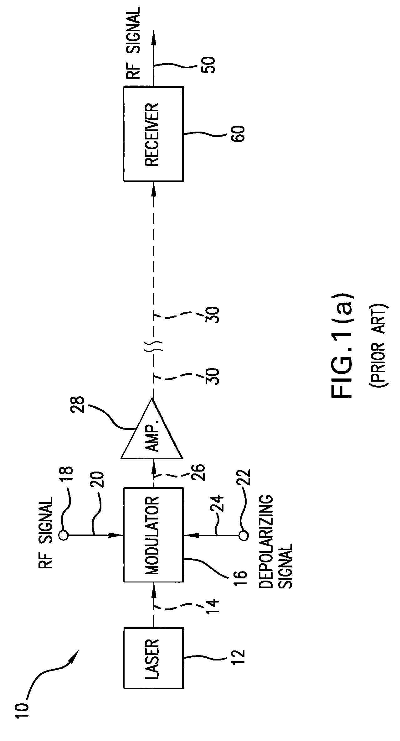
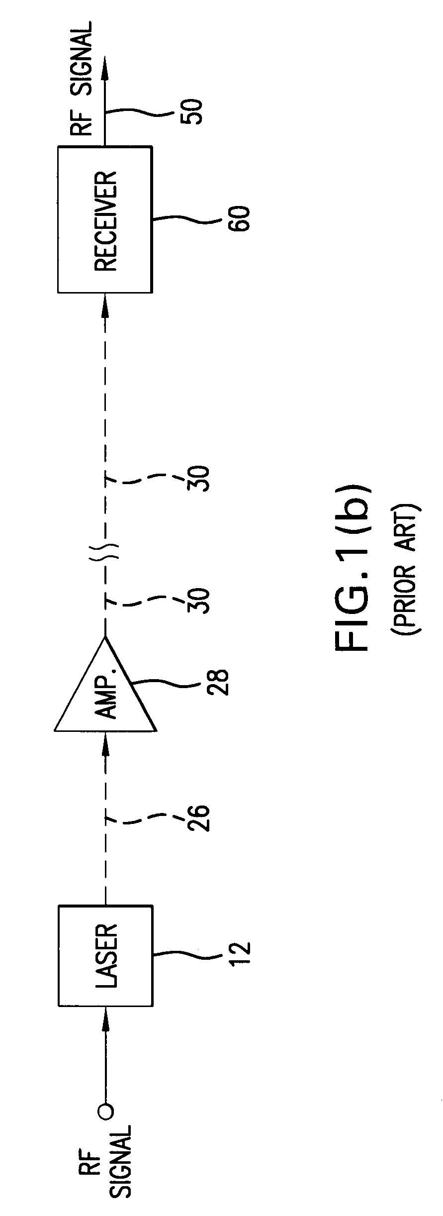
[0030]FIG. 1(a) is a block diagram of a prior art optical transmitter as represented in the U.S. Pat. No. 5,699,179 utilizing an external modulator. The transmitter, shown generally at 10, transmits an optical signal to a receiver 60 over an optical fiber path 30. The transmitter 10 includes a semiconductor laser 12, which produces a continuous wave (CW) output. Typical examples of such lasers are distributed feedback (DFB) laser / or Fabry-Perot lasers, t...


PUM


Abstract

An optical transmitter for generating a modulated optical signal for transmission over a fiber optic link to a remote receiver including a laser; a modulator for directly amplitude modulating the laser with an analog RF signal to produce an optical signal including an amplitude modulated information-containing component; and a phase modulator coupled to the output of the laser for canceling the noise signals generated in the laser.

Description

REFERENCE TO RELATED APPLICATIONS[0001]This application is a continuation-in-part of U.S. patent application Ser. No. 11 / 366,936 filed Mar. 2, 2006.[0002]This application is also related to U.S. patent application Ser. No. 10 / 946,056 filed Sep. 21, 2004, and assigned to the common assignee.BACKGROUND OF THE INVENTION[0003]1. Field of the Invention[0004]This invention relates to an optical transmission system for analog signals, and in particular to either a directly modulated or externally modulated solid-state laser. Moreover, the invention related to the cancellation of white noise components arising from a number of possible sources such as Brownian motion of charge carriers within the semiconductor laser (white noise) or noise arising from fluctuations in the bias current or the thermal environment of the laser (which varies inversely with frequency and therefore is typically referred to as “1 / f” noise.[0005]2. Description of the Related Art[0006]Directly modulating the analog i...

Claims


Application Information

Patent Timeline
IPC IPC(8): H04B10/04
CPCH04B10/505H04B10/5051H04B10/58H04B10/50597H04B10/50593
Inventor IANNELLI, JOHN
Owner EMCORE INC
Why Eureka
Try Eureka