Multipoint ignition engine

Active Publication Date: 2007-09-13
MIYAMA
View PDF39 Cites 32 Cited by
  • Summary
  • Abstract
  • Description
  • Claims
  • Application Information

AI Technical Summary

Benefits of technology

[0009]According to this invention, the evenly mixed air-fuel mixture is ignited using both the central spark gap and the plurality of peripheral spark gaps, and therefore the air-fuel mixture can be burned rapidly. Since rapid combustion is possible, ignition can be performed at a

Problems solved by technology

However, it has been learned that with a method of performing ignition using a plurality of spark gaps disposed on the periphery of a combustion chamber, the flames begin to interf

Method used


Image

  • Multipoint ignition engine
  • Multipoint ignition engine
  • Multipoint ignition engine

Examples


first embodiment

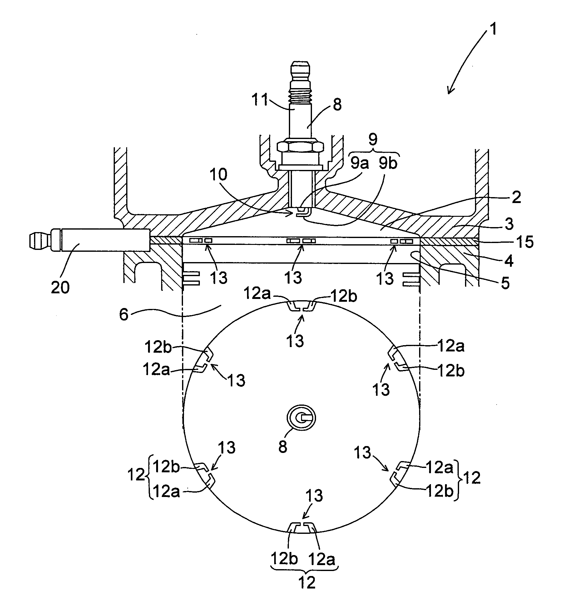
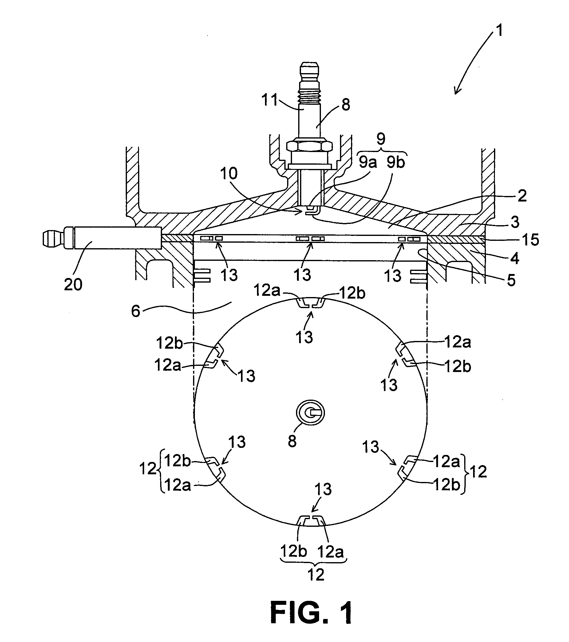
[0036]FIG. 1 shows the schematic constitution of a multipoint ignition engine 1 according to this invention.

[0037]In this embodiment, an engine 1 is a premix engine in which fuel injected through an injector attached to an intake port, not shown in the drawing, is mixed evenly with air, whereupon the air-fuel mixture is introduced into a combustion chamber 2, ignited by spark ignition, and burned. To obtain a desired air-fuel ratio, an intake air amount and the amount of fuel injected by the injector are adjusted. As will be described below, the engine 1 may be a direct injection engine. To improve the fuel efficiency, the air-fuel ratio of the air-fuel mixture is set higher than the stoichiometric air-fuel ratio (at an excess air ratio of approximately 2, for example), but to ensure the output of the engine 1, the air-fuel ratio of the air-fuel mixture may be set equal to or smaller (richer) than the stoichiometric air-fuel ratio depending on the operating region or in the entire o...

second embodiment

[0076]To further improve the output and fuel efficiency of the multipoint ignition engine 1 described above, the compression ratio of the engine 1 may be raised by reducing the thickness of the head gasket 15. As the compression ratio rises, the thermal efficiency improves, leading to improvements in output and fuel efficiency. However, when the thickness of the head gasket 15 is reduced, the distance between the peripheral spark gap 13 and the cylinder head 3 and so on decreases, leading to an increase in the possibility of leakage. Leakage occurs particularly frequently when the thickness of the head gasket 15 is set at 6 mm or less. This applies similarly when the capacitance of the ignition coil is increased.

[0077]In the second embodiment, as shown in FIGS. 7 and 8, leakage from the peripheral spark gaps 13 to the cylinder head 3 and the crown surface of the piston 6 is suppressed by forming leakage-preventing indentations 23, 24 respectively in positions corresponding to the ci...

third embodiment

[0080]To suppress leakage from the peripheral spark gaps 13 into the cylinder head 3 and so on, the third embodiment differs from the first embodiment in the structure of the peripheral electrode pair 12. All other structures are identical to the first embodiment.

[0081]FIG. 11 shows the structure of the peripheral electrode pair 12 according to the third embodiment. The part of the peripheral electrode pair 12 that is exposed to the interior of the combustion chamber 2 takes a linear rod form and does not have a curved portion midway. Further, the peripheral spark gap 13 is formed by causing the tip end surface of one of the electrodes (the earth electrode 12b) constituting the peripheral electrode pair 12 to face the tip end-side side face of the other electrode (the conducting electrode 12a), with a gap therebetween. The angle formed by the exposed parts of the electrodes 12a, 12b is substantially 90°.

[0082]With this structure, the likelihood of leakage from a midway point on the ...


PUM


Abstract

A multipoint ignition engine (1) includes a central electrode pair (9), disposed in the center of a combustion chamber (2), for forming a central spark gap (10), and a plurality of peripheral electrode pairs (12) held in a head gasket (15), which has an opening portion having a substantially identical diameter to an opening portion of a cylinder (5) in a position corresponding to the opening portion of the cylinder (5), for forming a plurality of peripheral spark gaps (13) around the inner periphery of the opening portion in the cylinder (5). An air-fuel mixture in the combustion chamber (2), which is obtained by mixing together fuel and air evenly to the stoichiometric air-fuel ratio or a richer/leaner air-fuel ratio than the stoichiometric air-fuel ratio, is ignited using both the central spark gap (10) and the plurality of peripheral spark gaps (13).

Description

FIELD OF THE INVENTION[0001]This invention relates to a multipoint ignition engine having a plurality of spark gaps in relation to a single combustion chamber.BACKGROUND OF THE INVENTION[0002]In a spark ignition engine, an air-fuel mixture in a combustion chamber is ignited by a spark plug, and conventionally, the spark plug is ideally attached to the center of the combustion chamber. When ignition is performed in the center, the resulting flame propagates concentrically from the center toward the periphery.[0003]Having approached the periphery, however, the flame is cooled by the wall surface of the combustion chamber and may be extinguished as a result. If the flame is extinguished, unburned gas is discharged as is through an exhaust valve. When the excess air ratio is approximately 1.7, for example, the fuel concentration of the air-fuel mixture in a cylinder is approximately 90,000 ppm, and when the flame is extinguished on the peripheral portion, the amount of hydrocarbon disch...

Claims


Application Information

Patent Timeline
IPC IPC(8): F02P15/02H01T13/46F02P15/08
CPCF02B2023/085F02P5/00F02P13/00H01T13/462F02P15/08H01T13/39F02P15/02
Inventor MINAMI, KATSUAKI
Owner MIYAMA
Why Eureka
Try Eureka