Heat exchanging tube with spiral groove

Inactive Publication Date: 2007-09-13
BEIJING U BRIDGE CHAOYANG
View PDF5 Cites 28 Cited by
  • Summary
  • Abstract
  • Description
  • Claims
  • Application Information

AI Technical Summary

Benefits of technology

[0005]The present invention aims to provide a heat transfer tube with higher thermal efficiency for improving the situation that the current heat transfer tube with spiral groove in circular sectiona

Problems solved by technology

In other words, the conversion from laminar flow into turbulence generates ahead of time, and violent turbulence makes dirt severely scoured within the tube.
As a result, fouling of the s

Method used


Image

  • Heat exchanging tube with spiral groove
  • Heat exchanging tube with spiral groove
  • Heat exchanging tube with spiral groove

Examples


Example

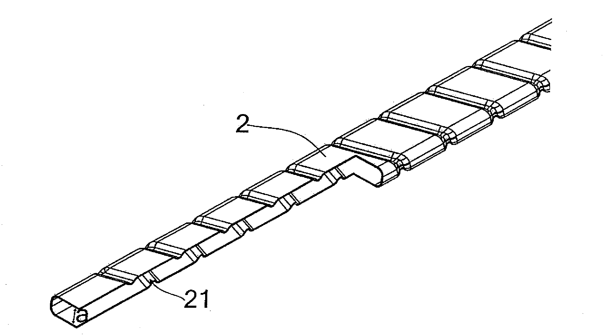
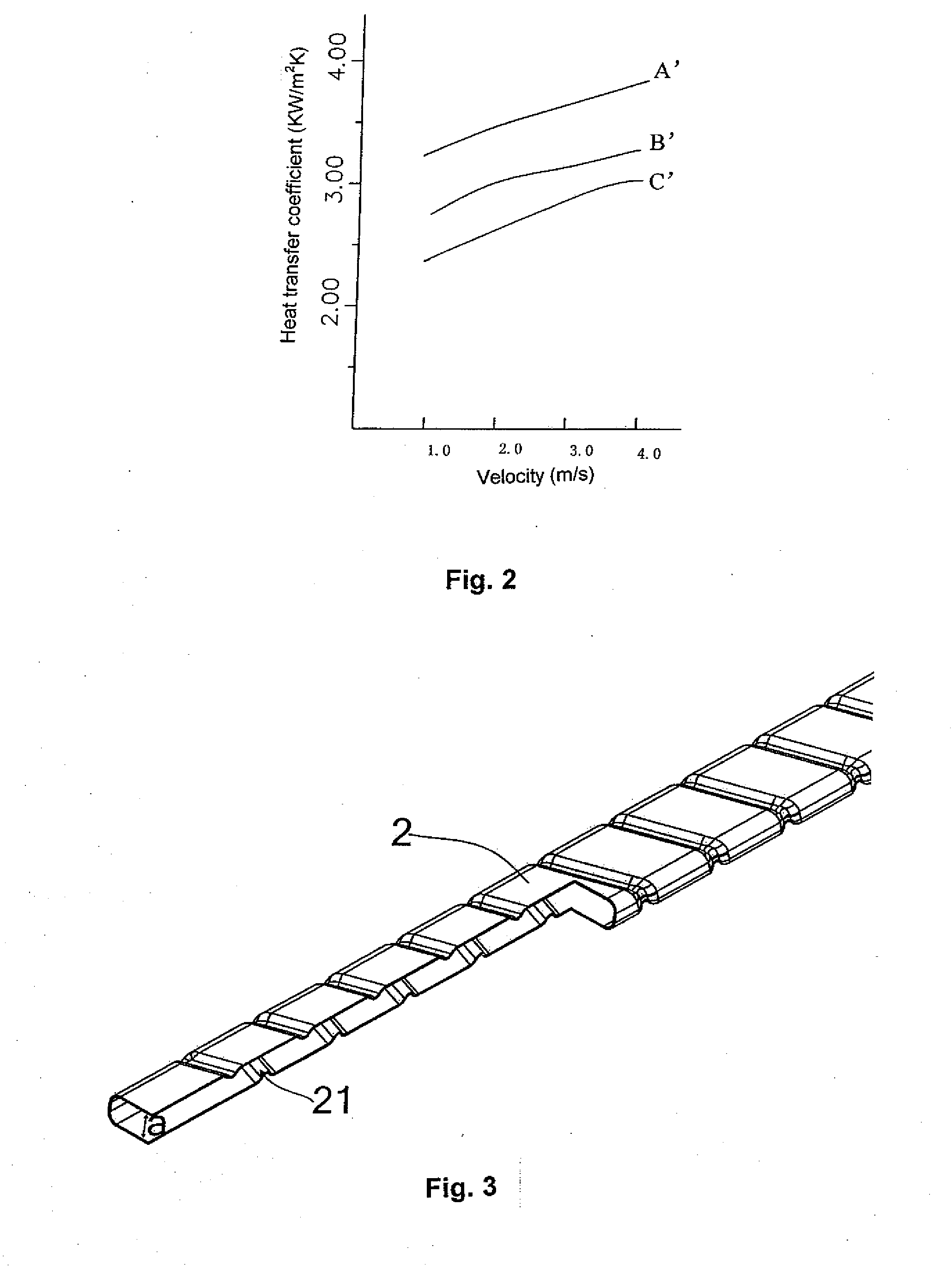
[0024]FIG. 3 and FIG. 4 are the sketch of the three dimensional drawing and the sectional view drawing of the first embodiment in the present invention respectively. In the drawings, heat transfer tube is a stainless steel tube body 2 with an internally convex spiral groove 21 on its surface. In order to realize the heat exchange with the largest efficiency by using the surface of the heat transfer tube sufficiently, and make it easy to be manufactured, the two adjacent surfaces of the heat tube are set to be connected by arc transition with the radius of R in this embodiment. Removing the sectional shape from the section of said heat transfer tube, the sectional shape of the stainless steel tube body 2 becomes rectangle, wherein the height is not equal to the width, and the adjacent two sides are connected by arc transition, which is shown in FIG. 4, wherein a is the height of the section; the spiral convex can be one or more; the sectional shape of the spiral groove can be set as ...


PUM

PropertyMeasurementUnit
Shapeaaaaaaaaaa
Widthaaaaaaaaaa
Heightaaaaaaaaaa

Abstract

The present invention relates to a heat transfer tube with spiral groove, comprising a stainless steel tube body with inward convex spiral groove on surface, wherein the stainless steel tube body possesses unequal height and width in the cross sectional view. In the EGR (Exhaust Gas Recirculation) cooling system for automotive engine, such kind of spiral groove tube with the unequal height and width in the cross-section acting as the heat transfer tube for the cooler make the cooler gain higher heat transfer effect, and it is hard to make dirt deposited inside or outside the tube, which greatly improves the emissions performance for automotive engine, and satisfies higher requirement of environmental protection.

Description

CROSS-REFERENCE TO RELATED APPLICATION [0001]This application claims priority benefit of Chinese patent application No. 200610057223.7 filed on Mar. 9, 2006, the contents of which is hereby incorporated by reference in its entirety.FIELD OF THE INVENTION [0002]The present invention relates to a heat transfer tube with spiral groove, in particular a heat transfer tube with spiral groove applied in the EGR (Exhaust Gas recirculation) cooling system for automotive engine, and its cross-section has unequal height and width.DESCRIPTION OF RELATED ART[0003]The EGR cooling technique is an effective and reliable technique to decrease nitrogen oxides (NOx) emissions of diesel engine. The theory is: decreasing the temperature of the exhaust gas by the cooler, and then returning the gas to the engine combustor in order to decrease the temperature of the combustor so as to reduce nitrogen oxides' generation and emissions. Among them, the cooler is the key element in the EGR system, and the heat...

Claims


Application Information

Patent Timeline
IPC IPC(8): F28F13/12
CPCF02M25/0714F02M25/0734F28D7/026F28D7/106Y02T10/121F28F1/02F28F1/06F28F13/06F28D21/0003F02M26/11F02M26/29
Inventor JING, JIANZHOUYANG, XIAOAISHEN, DONGHAOJING, JIANKUN
Owner BEIJING U BRIDGE CHAOYANG
Why Eureka
Try Eureka