
Method and apparatus for measuring oxygen concentration

Inactive Publication Date: 2007-09-13
CRYOVAC INC
View PDF40 Cites 53 Cited by
  • Summary
  • Abstract
  • Description
  • Claims
  • Application Information

AI Technical Summary

Benefits of technology

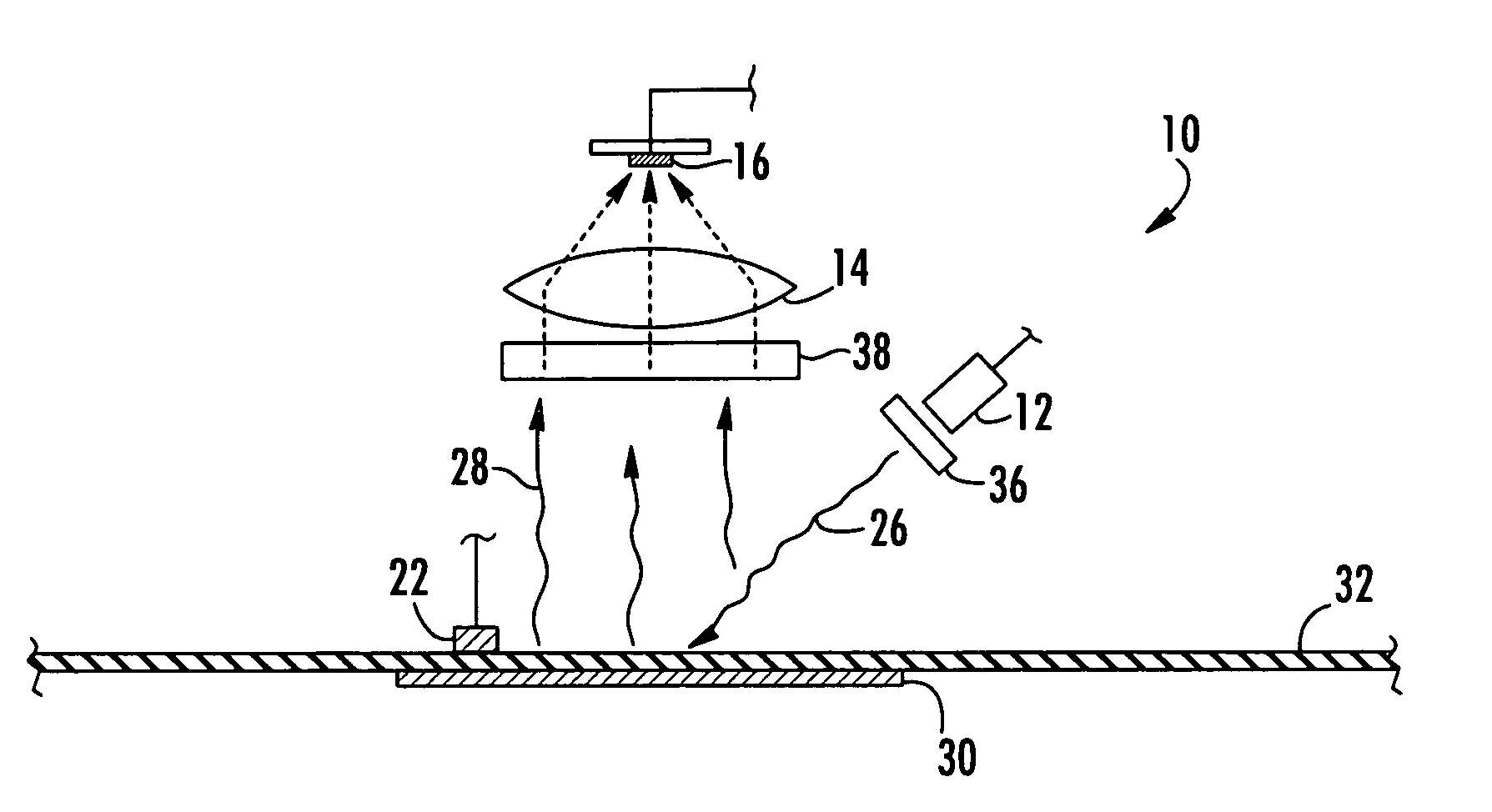
[0018] The method and apparatus use a luminescent compound that is disposed in the interior of the container. Exciting the luminescent compound results in a luminescent emission that may be measured externally from the container's interior. As a result, the oxygen concentration may be measured within a container without having to penetrate or physically damage the container. In one embodiment, the luminescent compound comprises a metal porphyrin that undergoes a phosphorescent transition.
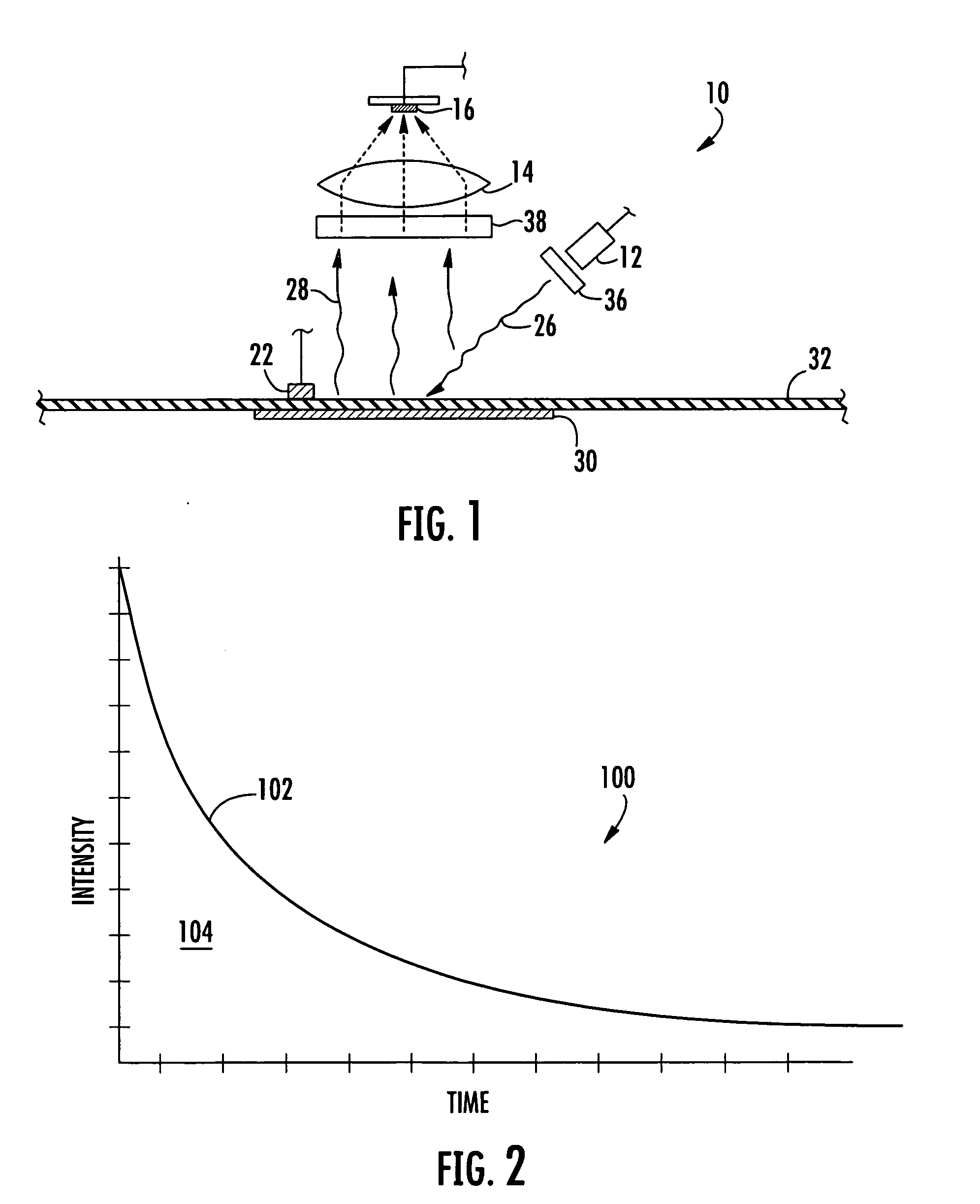
[0020] In one embodiment, tau can be calculated from the area of the decay curve. In some embodiments, the area of exponential decay curve is calculated by measuring luminescent intensity over a period of time in which intensity measurements are taken every 1 to 100 microseconds to create a plurality of discrete time segments. The irradiation and measurement steps may then be repeated n number of times, wherein n is from about 10 to 2500 to create n number of discrete time segments. The time segments may then be summed to create an average signal for n number of times. Averaging the signal helps to reduce the level of noise and thereby increase the sensitivity of the method and apparatus.
[0022] In yet another embodiment, the invention includes an apparatus for measuring oxygen concentration. In one embodiment, the apparatus may include an excitation source that is configured to generate excitation light having a wavelength that causes a luminescent compound to be promoted into an excited energy state. A detector disposed in a position to receive luminescent light emitted by the excited luminescent compound converts the luminescent light into an electronic signal. A control unit in communication with the detector then uses one or more algorithms to calculate the oxygen concentration within the container being examined. The use of a luminescent compound permits the analysis of the composition without having to penetrate or damage the container.
[0023] In one embodiment, the apparatus may also include focusing optics disposed between the detector and the luminescent compound. The focusing optics may be configured to collect and intensify the luminescent light against the detector so that the signal of the luminescent light may be magnified without the use of electronic amplifiers. As a result, the apparatus may have increased sensitivity independent of electronic amplifiers.
[0028] The Applicants have also discovered that limiting heat from the surrounding environment and from the electronics of the apparatus may help improve the accuracy of the calculated oxygen concentration. To help improve the accuracy of the temperature measurement the apparatus may include an insulating member that is disposed between the apparatus housing and an outer surface of the container. The insulating member helps thermally isolate the container from the housing. One or more temperature sensors may be disposed adjacent to the insulating member so that the temperature sensors are also thermally isolated from the housing. The insulating member may also help thermally isolate the temperature sensors from the surrounding environment. The insulating member can comprise any suitable material that can be used to thermally isolate the temperature sensors. Suitable materials may include thermoplastic or thermoset polymeric materials.
[0029] In another embodiment, the apparatus may comprise a handheld device that may permit a user to relatively easily manipulate and position the apparatus in a oxygen measuring relationship with a container that is being examined. In one embodiment, the handheld device may have a “gun-like” shape. The apparatus may also include a user interface panel having a visual display and a user interface which may permit an operator to scroll through and select various menu options.

Problems solved by technology

Foods, beverages, pharmaceuticals, medical devices, corrodible metals, analytical chemicals, electronic devices, and many other products may perish or experience diminished shelf life when stored too long in the presence of oxygen.
Unfortunately, oxygen scavengers do not always activate on command.
This may result from a number of factors, including defective scavenger compositions, inadequate triggering conditions, operator error, or a combination of these or other factors.
In many instances, it may not be readily apparent whether the oxygen scavenging composition is defective or whether the failure originated in the triggering equipment.
The longer a failed triggering attempt remains undiscovered, the more waste and expense is incurred, especially where packaging equipment operates at high speeds.
In addition, defective seals or openings in the packaging may permit oxygen to enter into the headspace within a package.
Such defective packages may not be easily discernable.
As a result, a packaged article may be exposed to an undesirable level of oxygen, which may result in loss of shelf-life or spoilage.
Also, sachets potentially introduce contaminants or other substances into the package that may be incompatible with its contents or accidentally ingested.
Unfortunately, the use of probes that rely on gas chromatography and other such analytical techniques typically requires removing a sample of the atmosphere within the package.
The device inevitably leaves a hole in the package, destroying the integrity of the package.
As a result, this may require sacrificing the sampled package.
As a result, prior art devices utilizing the Stern-Volmer equation to determine oxygen concentration have been limited to isothermal conditions.
Measuring the intensity or lifetime at temperature conditions that are different from the initial Stern-Volmer plot may produce results that are inaccurate and do not reflect the actual oxygen concentration.

Method used


Image

  • Method and apparatus for measuring oxygen concentration
  • Method and apparatus for measuring oxygen concentration
  • Method and apparatus for measuring oxygen concentration

Examples


examples

[0118] The following examples are provided for illustrative purposes only and should not be construed as limiting the invention.

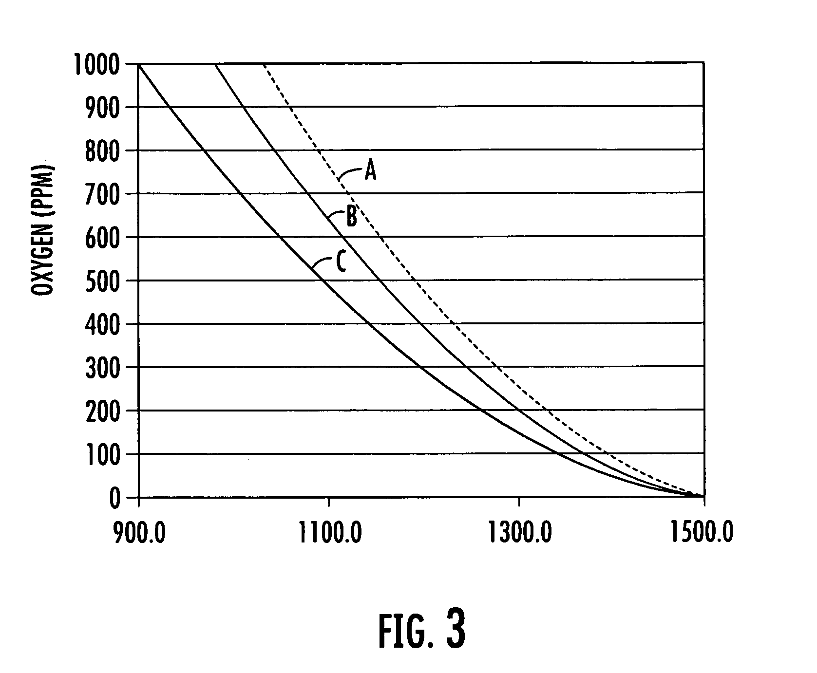
[0119] In the following examples a palladium porphyrin was placed into a temperature controlled chamber through which a stream of gas having a known oxygen concentration was introduced into the chamber. The chamber included a window onto which an apparatus in accordance with the invention was placed in an oxygen and temperature monitoring relationship with the porphyrin. The porphyrin was exposed to a light at a peak wavelength around 380 nanometers. The luminescence of the excited porphyrin was measured over a period of time ranging between 0 and 8,000 μs to produce an exponential decay. For each measurement the excitation and luminescence cycle of the porphyrin was repeated 1000 times. The baseline signal was determined at a time that is about 5,000 tau. The resulting cycles were averaged from which tau was calculated. Temperature was determined with a R...


PUM


Abstract

An apparatus and non-invasive method of measuring oxygen by exciting a luminescent compound disposed in a container and then measuring the intensity of the light emitted by the excited luminescent compound as it relaxes to the ground state. A plot of emission intensity as a function of time results in an exponential decay curve the area of which is inversely proportional to the oxygen concentration. The oxygen concentration can be determined over a wide temperature range by measuring the temperature of the container and the emission intensity and then applying the following equation: [O2]=(ATa(T)2+BTa(T)+CTa)(tau)2+(ATb(T)2+BTb(T)+CTb)(tau)+(ATc(T)2+BTc(T)+CTc) T is the measured temperature; tau is the area of the exponential decay curve; and ATa, BTa, CTa, ATb, BTb, CTb, ATc, BTc, and CTc are coefficients that are specific to the luminescent compound being examined.

Description

FIELD OF THE INVENTION [0001] The invention relates generally to oxygen concentration measurements and more particularly to oxygen concentration measurements within packaging materials that are measured by using an oxygen sensitive luminescent compound. BACKGROUND OF THE INVENTION [0002] It is generally known that reducing the exposure to oxygen of oxygen sensitive articles maintains and enhances the quality and shelf life of the article. For instance, reducing the oxygen exposure of oxygen sensitive food products in a packaging system maintains the quality of the food product and avoids food spoilage. Foods, beverages, pharmaceuticals, medical devices, corrodible metals, analytical chemicals, electronic devices, and many other products may perish or experience diminished shelf life when stored too long in the presence of oxygen. Reduced oxygen exposure may help keep the product in inventory longer, thereby reducing costs incurred from waste and having to restock. [0003] Manufacture...

Claims


Application Information

Patent Timeline
IPC IPC(8): G01N21/76
CPCG01M3/226G01M3/38G01N21/6408G01N21/643G01N31/225Y10T436/20G01N2021/6432G01N2021/6478G01N2201/0221G01N2201/1211G01N31/229
Inventor HAVENS, MARVIN RUSSELLAUSTIN, DARRELL CARLPAUL, DOUGLAS JAMES
Owner CRYOVAC INC
Learn More