Exterior coatings for golf balls

a golf ball and outer coating technology, applied in the field of golf balls, can solve the problems of insufficient surface area increase, uneven surface, and reducing desirable surface area, and achieve the effect of greatly reducing the cost of coating application

Inactive Publication Date: 2007-09-13
APPLIED MICROSTRUCTURES
View PDF7 Cites 48 Cited by
  • Summary
  • Abstract
  • Description
  • Claims
  • Application Information

AI Technical Summary

Benefits of technology

[0026] The present application is related to an exterior coating for application to a golf ball. In a first instance the exterior coating provides a hydrophobic surface on the golf ball. In a second instance the exterior coating provides a hydrophilic surface on the golf ball. Use of the disclosed method of coating deposition described below enables the precise control of process condit

Problems solved by technology

However, too great an RMS surface area is said to result in large surface peaks, widely spaced apart, which begins to diminish the desirable surface area for subsequent reaction with the chloroalkylsilane by vapor deposition.
Too small an RMS surface is said to result in the surface being too smooth, that is to say an insufficient increase in the surface area/or insuf

Method used


Image

  • Exterior coatings for golf balls
  • Exterior coatings for golf balls
  • Exterior coatings for golf balls

Examples


example one

[0084] Deposition of a Silicon Oxide Layer Having a Controlled Number of OH Reactive Sites Available on the Oxide Layer Surface

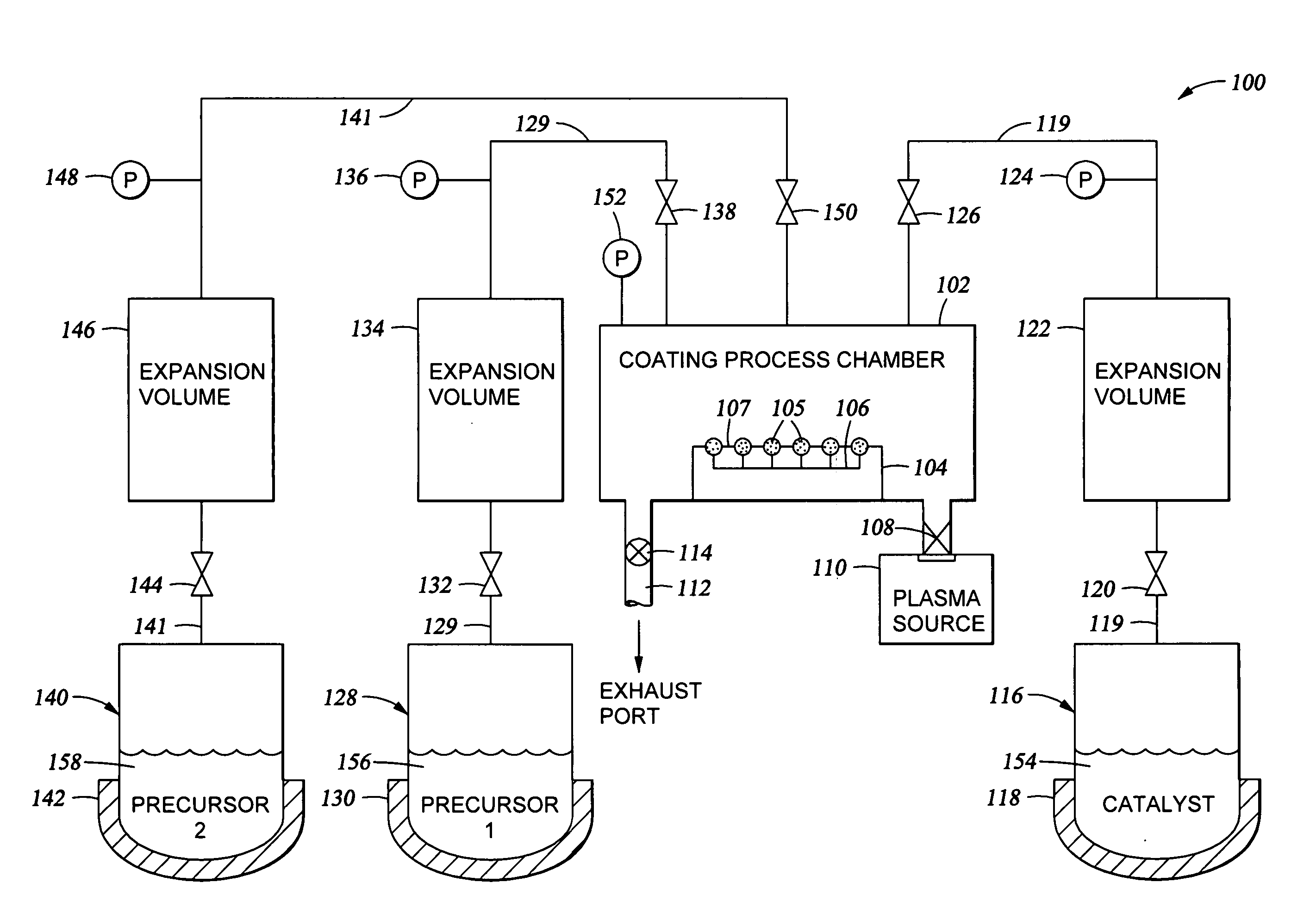
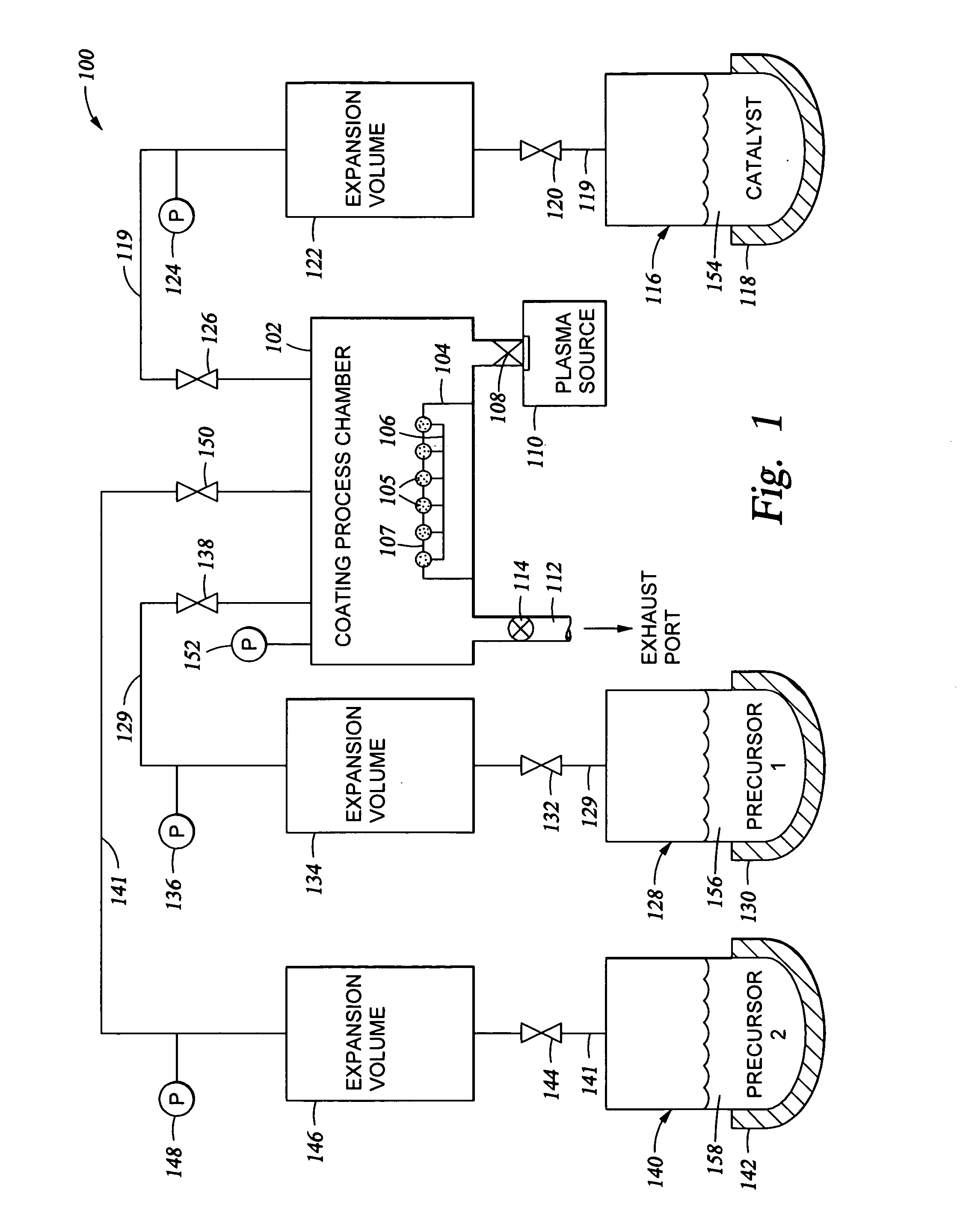
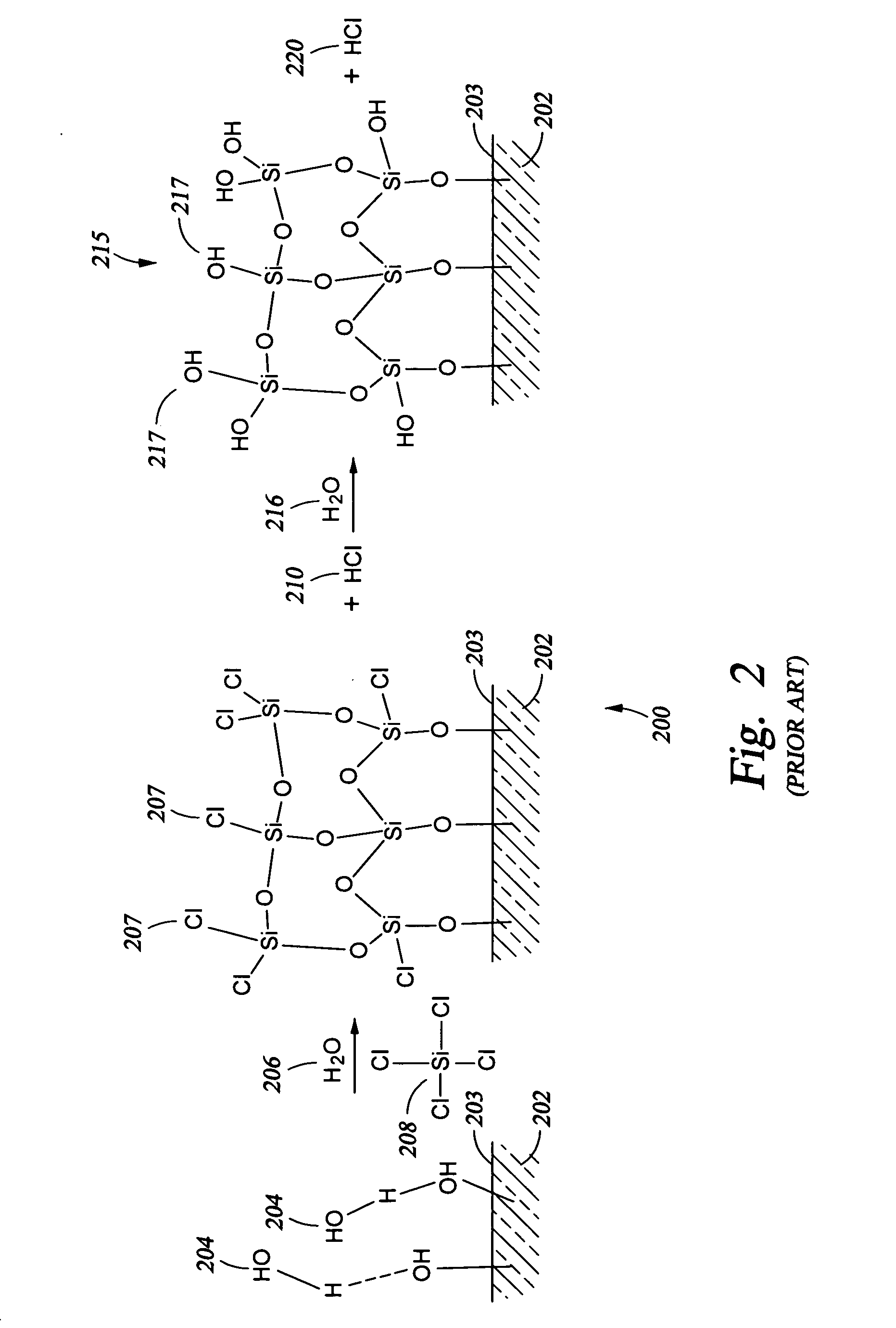
[0085]FIG. 2 shows a schematic 200 of the mechanism of bonding oxide layer formation. In particular, a substrate 202, plasma-cleaned golf ball layer surface, for example, may have some OH groups 204 present on the surface 203. A chlorosilane 208, such as the tetrachlorosilane shown, and water 206 are reacted with the OH groups 204, either simultaneously or in sequence, to produce the oxide layer 205 shown on surface 203 of substrate 202 and byproduct HCl 210. In addition to chlorosilane precursors, chlorosiloxanes, fluorosilanes, and fluorosiloxanes may be used to provide the oxide bonding layer.

[0086] Subsequently, the surface of the oxide layer 205 can be further reacted with water 216 to replace C1 atoms on the upper surface of oxide layer 205 with OH groups 217, to produce the hydroxylated layer 215 shown on surface 203 of substrate 202 and byproduct H...

example two

[0087] To evaluate process parameters useful in preparation of a silicon oxide bonding layer, silicon oxide layers were applied over a glass substrate. The glass substrate was treated with an oxygen plasma in the presence of residual moisture which was present in the process chamber (after pump down of the chamber to about 20 mTorr) to provide a clean surface (free from organic contaminants) and to provide the initial OH groups on the glass surface.

[0088] Various process conditions for the subsequent reaction of the OH groups on the glass surface with vaporous tetrachlorosilane and water are provided below in Table I, along with data related to the thickness and roughness of the oxide coating obtained and the contact angle (indicating hydrophobicity / hydrophilicity) obtained under the respective process conditions. A lower contact angle indicates increased hydrophilicity and an increase in the number of available OH groups on the silicon oxide surface.

TABLE IDeposition of a Silico...

example three

[0092] In the preferred embodiment discussed in detail below, the silicon oxide bonding layer was applied over golf ball having a polymeric cover layer of ionomer, which exhibited a contact angle coming out of the box which ranged between about 80° and about 90°. The golf ball was wiped with isopropyl alcohol to remove any grease or oils present on the golf ball surface. The golf ball surface was then treated with an oxygen plasma in the presence of residual moisture which was present in the process chamber (after pump down of the chamber to about 20 mTorr) to provide a clean surface (free from organic contaminants) and to provide the initial OH groups on the golf ball surface. In a process chamber of the kind described above, the flow rate of oxygen was about 400 sccm, and the RF power applied to create the plasma was about 200 W, with the exposure time of the golf ball being about 5 minutes at 35° C.

[0093] A silicon oxide coating of the kind described above was applied over the g...


PUM

PropertyMeasurementUnit
Thicknessaaaaaaaaaa
Thicknessaaaaaaaaaa
Thicknessaaaaaaaaaa

Abstract

Improved golf ball exterior coatings which are used to create an extremely uniform hydrophobic or hydrophilic exterior surface on the golf ball. When the surface of the golf ball is hydrophobic, it tends to repel water, and this reduces drag on the golf ball surface as the golf ball travels through the air. When the surface of the golf ball is hydrophilic, the surface of the golf ball wets uniformly and the ball rolls straighter on a wet green, as the forces acting on the ball are more uniform. The hydrophobic or hydrophilic exterior coating is applied to the golf ball using vapor-phase deposition in instances where strict control over coating thickness uniformity, and/or reduced surface roughness is desired.

Description

[0001] This application is related to a series of patent applications pertaining to the application of thin film coatings on various substrates, particularly including U.S. patent application Ser. No. 10 / 862,047, filed Jun. 4, 2004, and entitled “Controlled Deposition of Silicon-Containing Coatings Adhered by an Oxide Layer”; and, U.S. patent application Ser. No. 10 / 996,520, filed Nov. 19, 2004, and entitled “Controlled Vapor Deposition of Multilayered Coatings Adhered by an Oxide Layer”. Both of these applications are hereby incorporated by reference in their entireties.BACKGROUND OF THE INVENTION [0002] 1. Field of the Invention [0003] The present invention pertains to golf balls coated with exterior thin film coatings which affect the performance of the golf ball during play. [0004] 2. Brief Description of the Background Art [0005] This section describes background subject matter related to the invention, with the purpose of aiding one skilled in the art to better understand the ...

Claims


Application Information

Patent Timeline
IPC IPC(8): A63B37/00A63B37/14
CPCA63B37/0022A63B45/00B05D1/60C23C16/401B05D5/04B05D5/08B05D3/144A63B37/00221
Inventor CHINN, JEFFREY D.YANG, PETER PUI-WA
Owner APPLIED MICROSTRUCTURES
Why Eureka
Try Eureka