Methods and apparatus for reducing timing skew

a timing skew and apparatus technology, applied in the direction of cad circuit design, program control, instruments, etc., can solve the problems of increasing complexity and performance of system on a chip design, signal to signal timing skew typically exceeding the capabilities of existing routing tools, and the use of current tools is not adequate to route these critical interface paths with minimum skew. , to reduce the layout distance of each signal path, reduce timing skew, and reduce timing skew

Inactive Publication Date: 2007-09-20
BELL SEMICON LLC
View PDF12 Cites 12 Cited by
  • Summary
  • Abstract
  • Description
  • Claims
  • Application Information

AI Technical Summary

Benefits of technology

[0005] To these ends, an embodiment of the present invention includes a method for reducing timing skew. The method begins with identifying signals that are to have a reduced timing skew. These identified signals are then routed to reduce the layout distance of each signal path. Among these identified signals, a longest signal path is found and the signal paths of the remaining identified signals are lengthened. The lengthening is done to each of the remaining identified signal paths, so that all these paths have a length substantially equal to the length of the longest path, thereby reducing the timing skew between the identified signals.

Problems solved by technology

System on a chip designs continue to grow in complexity and performance as technology processes provide greater and greater densities.
With increased densities and more and more signal paths having strict timing requirements, the routing of the numerous signal paths with minimum capacitance and signal to signal timing skew typically exceeds the capabilities of existing routing tools.
Due to the complexities of current and future chip designs with thousands to millions of interconnecting wires, the use of current tools is not adequate to route these critical interface paths with minimum skew.
Data and clock signals in the DDR external memory interface propagate through the chips inputs and outputs, packaging, and printed circuit board paths which introduce noise on the signals.
Due to the noise and signal skew, the clocking point where data is valid in a receiver circuit is critical with little tolerance.

Method used


Image

  • Methods and apparatus for reducing timing skew
  • Methods and apparatus for reducing timing skew
  • Methods and apparatus for reducing timing skew

Examples


Embodiment Construction

[0016] The present invention will now be described more fully with reference to the accompanying drawings, in which several embodiments and various aspects of the invention are shown. This invention may, however, be embodied in various forms and should not be construed as being limited to the embodiments set forth herein. Rather, these embodiments are provided so that this disclosure will be thorough and complete, and will fully convey the scope of the invention to those skilled in the art.

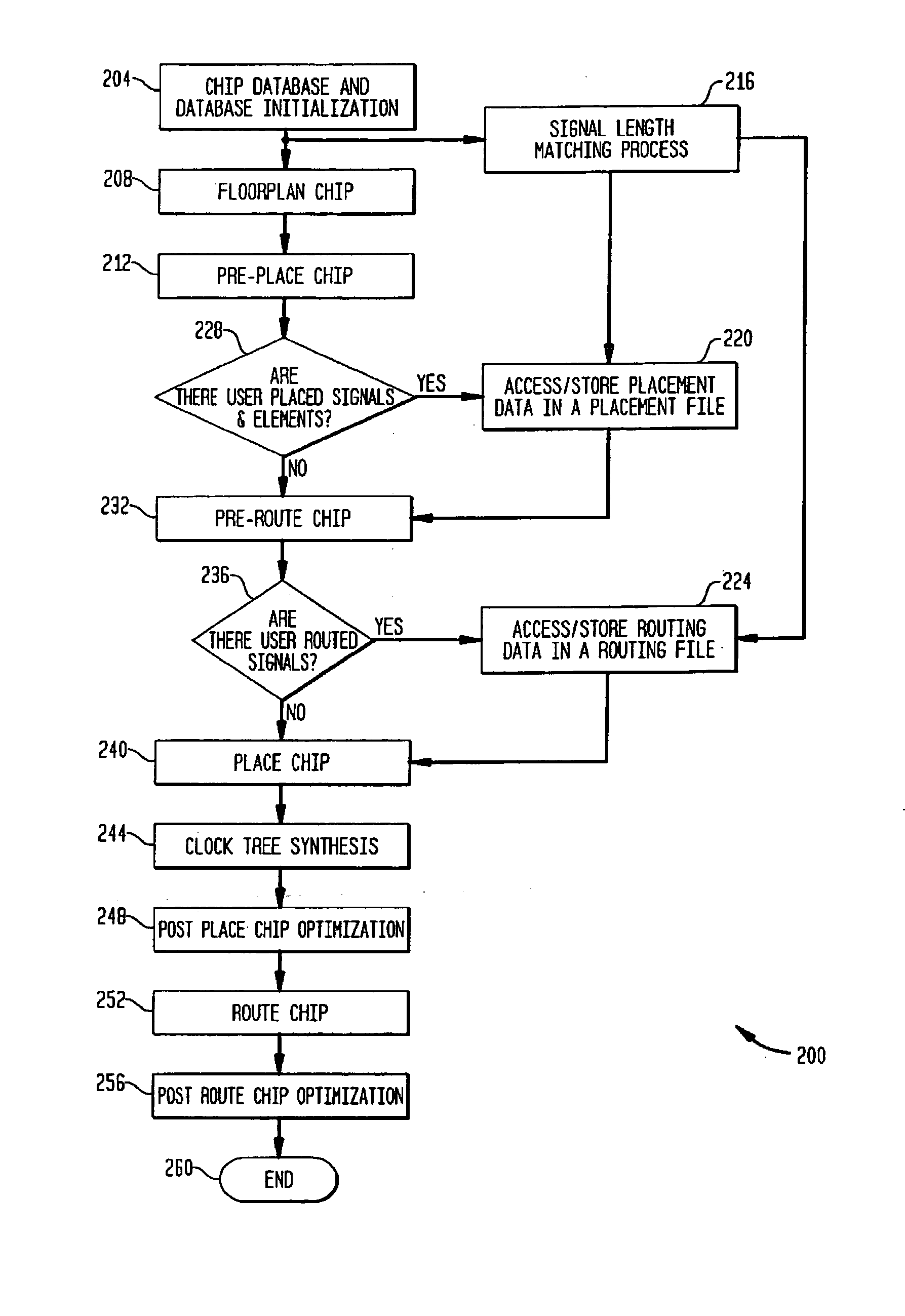
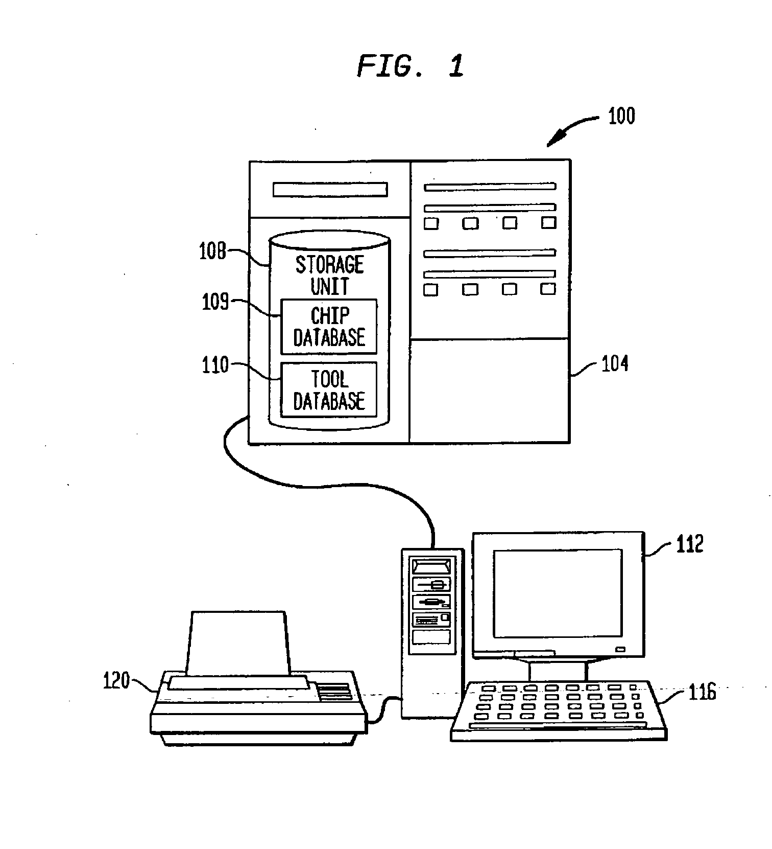
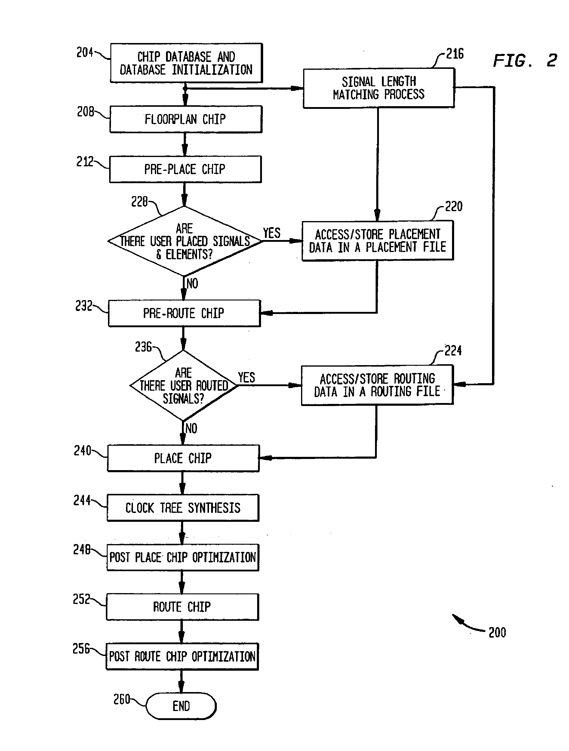
[0017]FIG. 1 illustrates a chip routing system 100 in accordance with the present invention. The chip routing system 100 uses a processor 104 which has a storage unit 108 for storing a chip database 109, a tools database 110, and the like, and interfaces with a monitor 112, keyboard 116, and printer 120. The processor 104 runs a high level place and route process and a signal length matching process as described in more detail below. While other programming languages, compilers, operating systems...


PUM


Abstract

Reducing timing skew begins with identifying signals that are to have a reduced timing skew. These identified signals are then routed to reduce the layout distance of each signal path. Among these identified signals, a longest signal path is found and the signal paths of the remaining identified signals are lengthened. The lengthening is done to each of the remaining identified signal paths to each have a length substantially equal to the longest signal path whereby the timing skew between the identified signals is reduced. A signal length matching process may be stored as a program in a computer-readable medium with the program operable on a computer system tailored for providing chip placement and routing processes.

Description

1. FIELD OF INVENTION [0001] The present invention relates generally to improved methods and apparatus for reducing timing skew, and more particularly to advantageous techniques for matching the lengths of multiple signal paths in an integrated circuit layout. 2. BACKGROUND OF INVENTION [0002] System on a chip designs continue to grow in complexity and performance as technology processes provide greater and greater densities. With increased densities and more and more signal paths having strict timing requirements, the routing of the numerous signal paths with minimum capacitance and signal to signal timing skew typically exceeds the capabilities of existing routing tools. The existing routing tools usually have features allowing special routing for data buses in order to reduce the skew between different data bits. The purpose of such a routing is to make sure that all the data bits in the bus are propagating to the destination within one clock cycle. Depending on the technology, r...

Claims


Application Information

Patent Timeline
Patent Type & Authority Applications(United States)
IPC IPC(8): G06F17/50
CPCG06F17/5031G06F2217/84G06F17/5045G06F30/3312G06F2119/12G06F30/30
Inventor DAVIDOVIC, GORAN
Owner BELL SEMICON LLC
Why Eureka
Try Eureka