

Process for the catalytic control of radical reaction
- Summary
- Abstract
- Description
- Claims
- Application Information
AI Technical Summary
Benefits of technology
Problems solved by technology
Method used
Image

Examples
examples
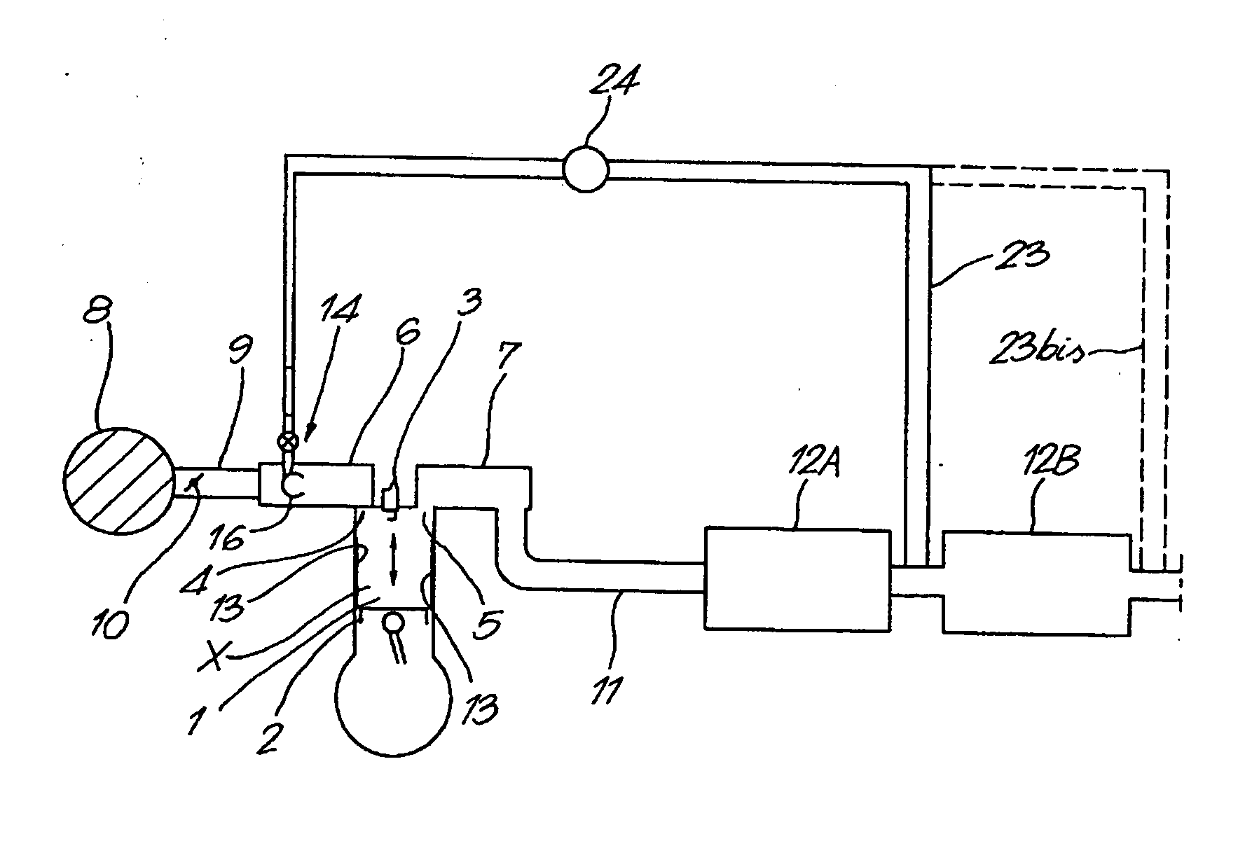
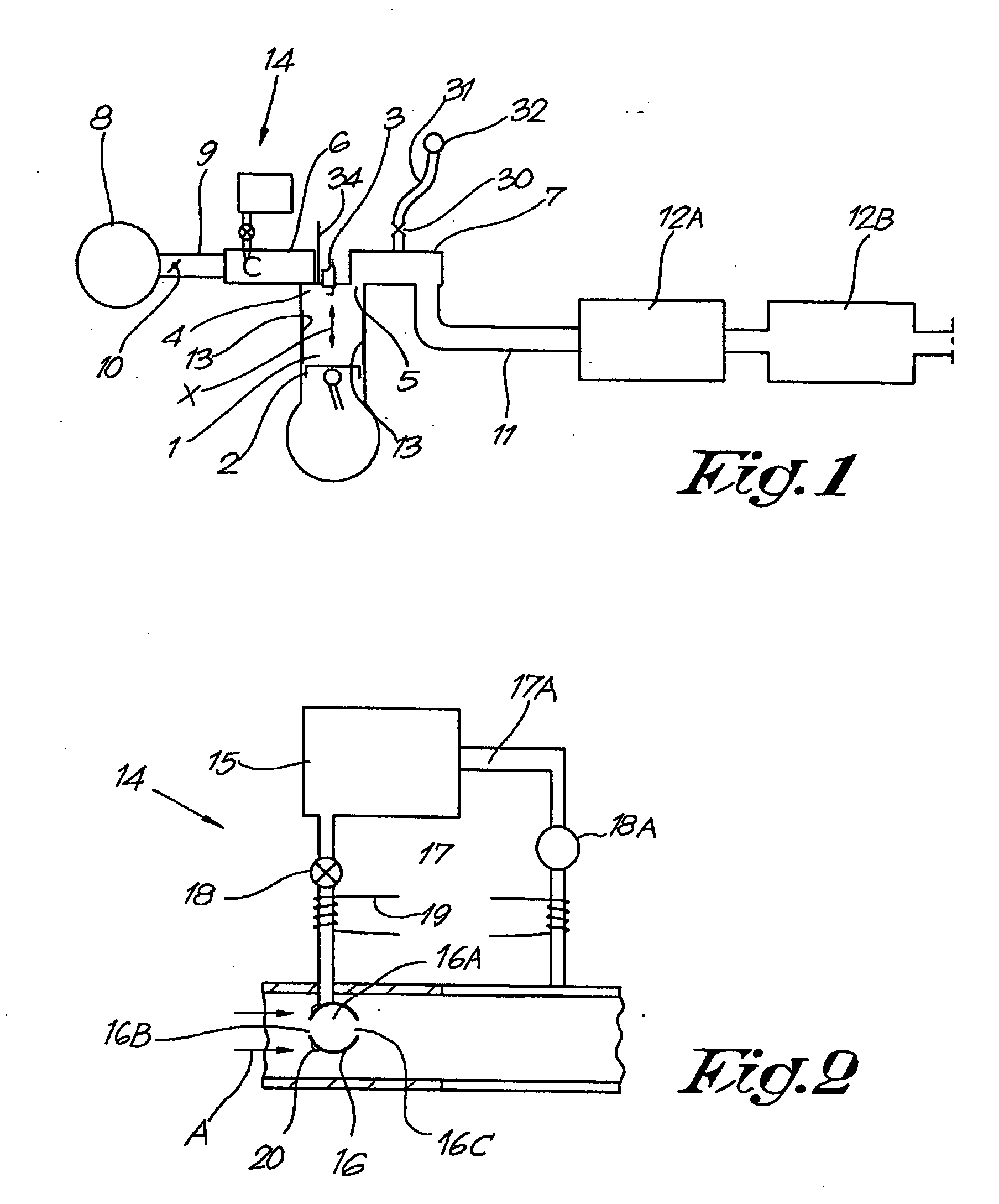
[0355] The motor of FIG. 1 comprises several chambers 1 in each of which a piston 2 is moved (arrow X). A spark plug 3 is used for the ignition of the mixture air-fuel present in the chamber 1. Valves 4,5 are actuated so as to allow the inlet of air and combustible in the chamber 2, the outlet of flue gases out of the chamber 2, as well as a possible flushing effect (the inlet valve or valves and the outlet valve or valves being in open position, whereby enabling air to cool the chamber and to remove some still present flue gases) as well as a cooling effect of the flue gases. The motor comprises also: an intake manifold 6, an outlet manifold 7, an air filter 8, a pipe 9 with possibly a valve or butterfly 10 for controlling the air or air-fuel consumption, an outlet pipe 11, a filtering system 12A for the flue gases (for example for further oxidizing thereof, for trapping particles, 3-ways catalyst system, etc) and a soot trap system 12B. The engine of FIG. 1 is a four stroke engine...
process scheme 1 (fig.22)
Process Scheme 1 (FIG. 22)
[0663] In this process, the regeneration or rejuvenation of the catalyst of the combustion chamber 1 is carried out so as to not induce the regeneration or rejuvenation of the soot collector 12B and whereby the regeneration or rejuvenation of the soot collector 12B is carried out intermittently when required. For example the cerium concentration in the flue gases is low enough during the regeneration of the catalyst of the burning chamber, that said cerium concentration is not sufficient for reducing the ignition temperature of the soot present in the soot collector below the temperature of the flue gases in contact with the soot, and / or the treatment of the catalyst of the burning chamber is carried during a period sufficient for regenerating the catalyst of the burning chamber, but said time being not sufficient for conveying a sufficient amount of cerium to the soot collector for reducing the ignition temperature of the soot in contact with the flue gase...
process scheme 2 (fig.23)
Process Scheme 2 (FIG. 23)
[0668] Water vapor with a minimum amount of cerium is admitted (for example by means of a device 14) in the inlet manifold (6) of the burning chamber (1), so as to ensure an intermittent regeneration of the catalyst present in the burning chamber. For example, the cerium added in the inlet manifold 6 (rate of admission controlled for example by the control unit of FIG. 12) is such that the flue gases comprise less than 2 ppm cerium, advantageously less than 1 ppm, such as 500 ppb, 200 ppb, 100 ppb or even lesser, for the regeneration.
[0669] When the regeneration or rejuvenation of the soot trap system is required, a further amount of cerium (increased rate of cerium admission) is admitted in the inlet manifold (6), so as to increase the cerium concentration in the flue gases to more than 2 ppm, advantageously more than 5 ppm, preferably more than 10 ppm, such as between 10 and 20 ppm. Said further amount of cerium (increased cerium admission rate) is added...
PUM
| Property | Measurement | Unit |
|---|---|---|
| Temperature | aaaaa | aaaaa |
| Length | aaaaa | aaaaa |
| Percent by mass | aaaaa | aaaaa |
Abstract
Description
Claims
Application Information