Etching method

a color filter and etching technology, applied in the field of etching methods, can solve the problem that the conventional etching process cannot effectively mass produce filters, and achieve the effect of increasing the etching ra

Inactive Publication Date: 2007-09-27
UNITED MICROELECTRONICS CORP
View PDF11 Cites 8 Cited by
  • Summary
  • Abstract
  • Description
  • Claims
  • Application Information

AI Technical Summary

Benefits of technology

[0009] Accordingly, at least one objective of the present invention is to provide a method for etching color filter capable of effectively increase the etching rate.

Problems solved by technology

Hence, the conventional etching process cannot effectively mass produce filters.

Method used


Image

  • Etching method
  • Etching method
  • Etching method

Examples


Embodiment Construction

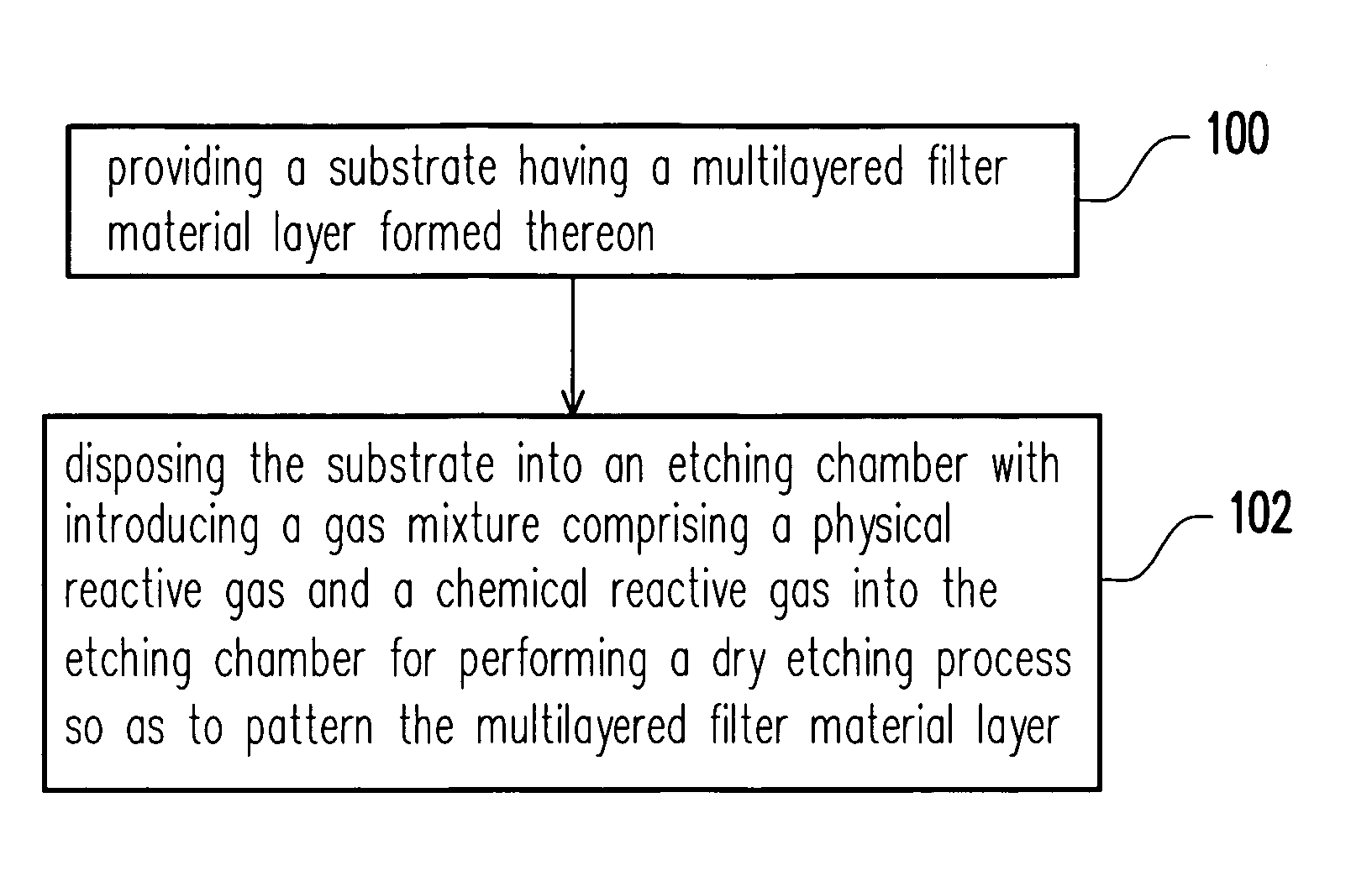
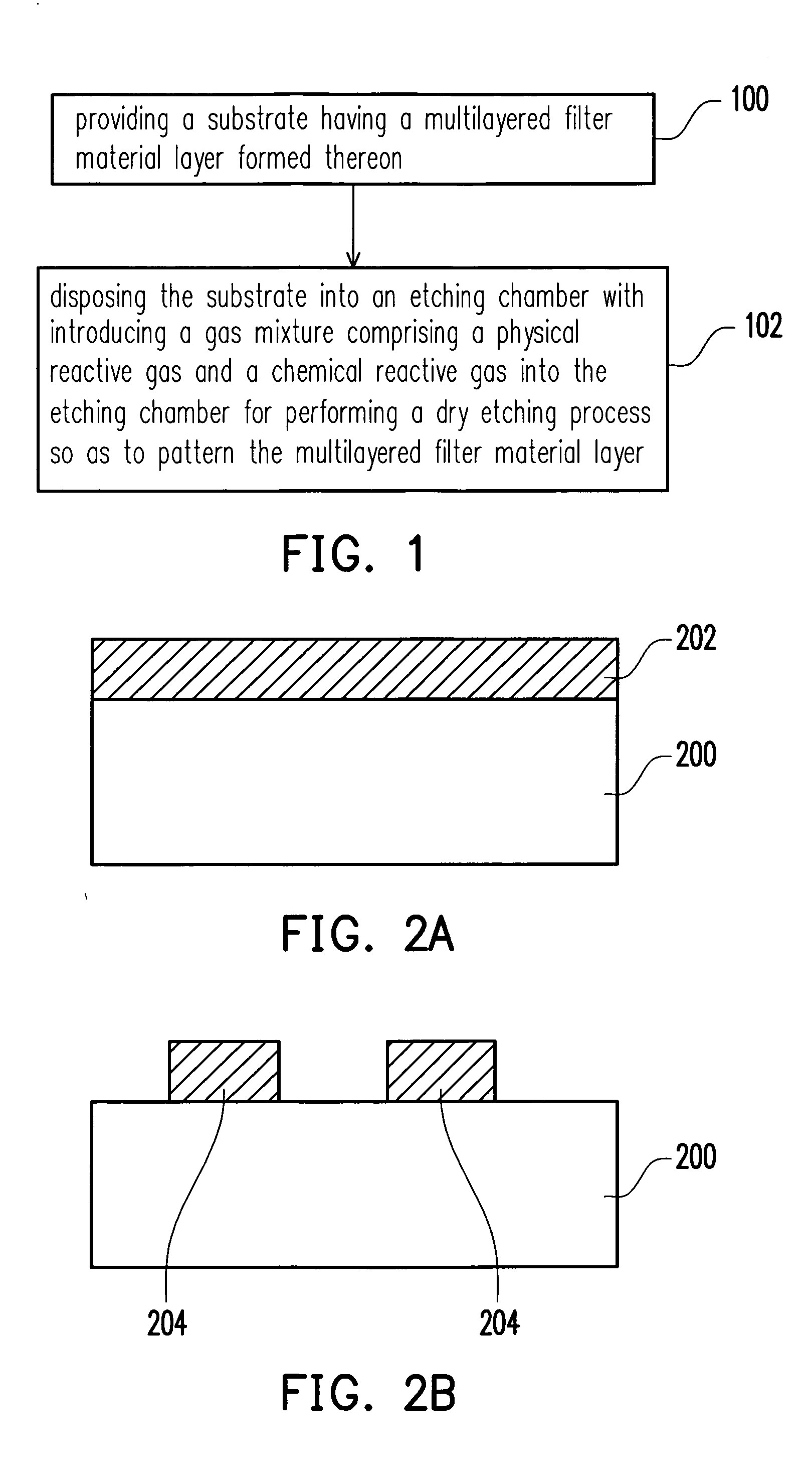
[0042]FIG. 1 is a flow chart showing an etching method according one embodiment of the present invention. As shown in FIG. 1, in the step 100, a substrate having a multilayered filter material layer and the well known semiconductor devices formed thereon is provided. The multilayered filter material layer can be, for example but not limited to, composed of several film layers which are interlacing and stacking to each other and possess different refraction indices from each other. The thickness of the multilayered filter material layer is about 8000 angstroms. For example, the multilayered filter material layer can be formed by stacking the film layers on the substrate in an order from the film layer with a relatively lower refraction index to the film layer with a relatively higher refraction index from the bottom to the top of the multilayered filter material layer. Alternatively, in another embodiment, the multilayered filter material layer can be, for example, formed by stacking...


PUM

PropertyMeasurementUnit
thicknessaaaaaaaaaa
thicknessaaaaaaaaaa
flow rateaaaaaaaaaa

Abstract

The invention is directed to a method for etching a color filter. The method comprises steps of providing a substrate having a multilayered filter material layer formed thereon and then disposing the substrate into an etching chamber with introducing a gas mixture into the etching chamber for performing a dry etching process so as to pattern the multilayered filter material layer, wherein the gas mixture comprises a physical reactive gas and a chemical reactive gas.

Description

BACKGROUND OF THE INVENTION [0001] 1. Field of Invention [0002] The present invention relates to a method for forming a optical device. More particularly, the present invention relates to a method for etching a color filter. [0003] 2. Description of Related Art [0004] Currently, the multimedia technology is well developed and is benefited from the improvement of the semiconductor device or the display device. As for the display, the liquid crystal display having superior features, such as high definition, good space utilization efficiency, low power consumption and no radiation, becomes the mainstream of the market. [0005] Liquid crystal display mainly comprised of a display panel and a back light module, wherein the display panel comprises an active array display substrate and a color filter. The color filter is used to filter the light transmitted from the back light module so as to make the liquid crystal display has the true color functionality. [0006] The color filter can be a ...

Claims


Application Information

Patent Timeline
Patent Type & Authority Applications(United States)
IPC IPC(8): C03C25/68B44C1/22
CPCG02B5/201G02F1/133516G02B5/223
Inventor WU, YI-TYNGYU, HUA-WEI
Owner UNITED MICROELECTRONICS CORP
Why Eureka
Try Eureka