
Quinoxaline derivative, and light-emitting element, light-emitting device, electronic device using the quinoxaline derivative

a technology of quinoxaline and quinoxaline, which is applied in the direction of discharge tube/lamp details, organic chemistry, discharge tube luminescnet screens, etc., can solve the problems of affecting the efficiency of light-emitting elements, etc., to achieve excellent thermal stability, electron transporting property and hole transporting property, excellent

Inactive Publication Date: 2007-09-27
SEMICON ENERGY LAB CO LTD
View PDF7 Cites 92 Cited by
  • Summary
  • Abstract
  • Description
  • Claims
  • Application Information

AI Technical Summary

Benefits of technology

[0017] In view of the aforementioned problems, it is an object of the present invention to provide a new bipolar organic compound, in particular, a bipolar organic compound having excellent thermal stability. Further, it is another object to provide a bipolar organic compound which is electrochemically stable.
[0018] Further, it is another object to provide a light-emitting element and a light-emitting device having low driving voltage and power consumption by using the bipolar organic compound of the present invention. In addition, it is another object to provide a light-emitting element and a light-emitting device having a long lifetime by using the bipolar organic compound of the present invention.
[0019] It is still another object to provide a long-life electronic device with low power consumption and high thermal stability by using the bipolar organic compound of the present invention.

Problems solved by technology

Such a light-emitting element has a lot of problems which depend on the organic materials.
As a result, change of emission spectrum and / or decrease in luminous efficiency may take place.
However, since their performances such as thermal stability are not satisfactory, bipolar organic compounds having high thermal stability have been required to be developed.

Method used


Image

  • Quinoxaline derivative, and light-emitting element, light-emitting device, electronic device using the quinoxaline derivative
  • Quinoxaline derivative, and light-emitting element, light-emitting device, electronic device using the quinoxaline derivative
  • Quinoxaline derivative, and light-emitting element, light-emitting device, electronic device using the quinoxaline derivative

Examples


embodiment mode 1

[0119] In this embodiment mode, a quinoxaline derivative of the present invention will be explained.

[0120] A quinoxaline derivative of the present invention is a quinoxaline derivative represented by a general formula (1).

formula [11]

wherein R1 to R4 each represent any of a hydrogen atom, an alkyl group having 1 to 4 carbon atoms, or an aryl group having 6 to 25 carbon atoms; R5 represents any of a hydrogen atom, an alkyl group having 1 to 4 carbon atoms, or an aryl group having 6 to 25 carbon atoms; Ar1 represents an aryl group having 6 to 25 carbon atoms; and a represents an arylene group having 6 to 25 carbon atoms. A represents a substituent represented by any of general formulas (1-1) to (1-3). In the general formulas (1-1) to (1-3), P represents an arylene group having 6 to 25 carbon atoms; Ar3 and Ar4 each represent an aryl group having 6 to 25 carbon atoms; Ar5 represents an aryl group having 6 to 25 carbon atoms; R31 represents any of a hydrogen atom, an alkyl group hav...

embodiment mode 2

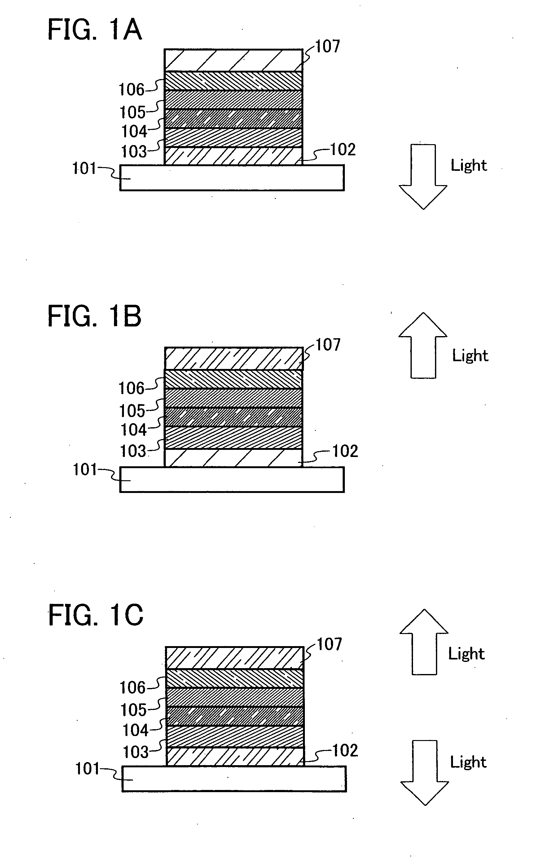
[0146] One mode of a light-emitting element using a quinoxaline derivative of the present invention will be explained below with reference to FIG. 1A.

[0147] A light-emitting element of the present invention has a plurality of layers between a pair of electrodes. The plurality of layers are fabricated by stacking layers comprising a substance having a high carrier injecting property and layers comprising substance having a high carrier transporting property. These layers are stacked so that a light-emitting region is located in a region away from the electrodes, that is, recombination of carriers is performed in an area away from the electrodes.

[0148] In this embodiment mode, a light-emitting element includes a first electrode 102, a first layer 103, a second layer 104, a third layer 105, and a fourth layer 106 which are sequentially stacked over the first electrode 102, and a second electrode 107 provided thereover. Following description will be provided regarding the first electr...

embodiment mode 3

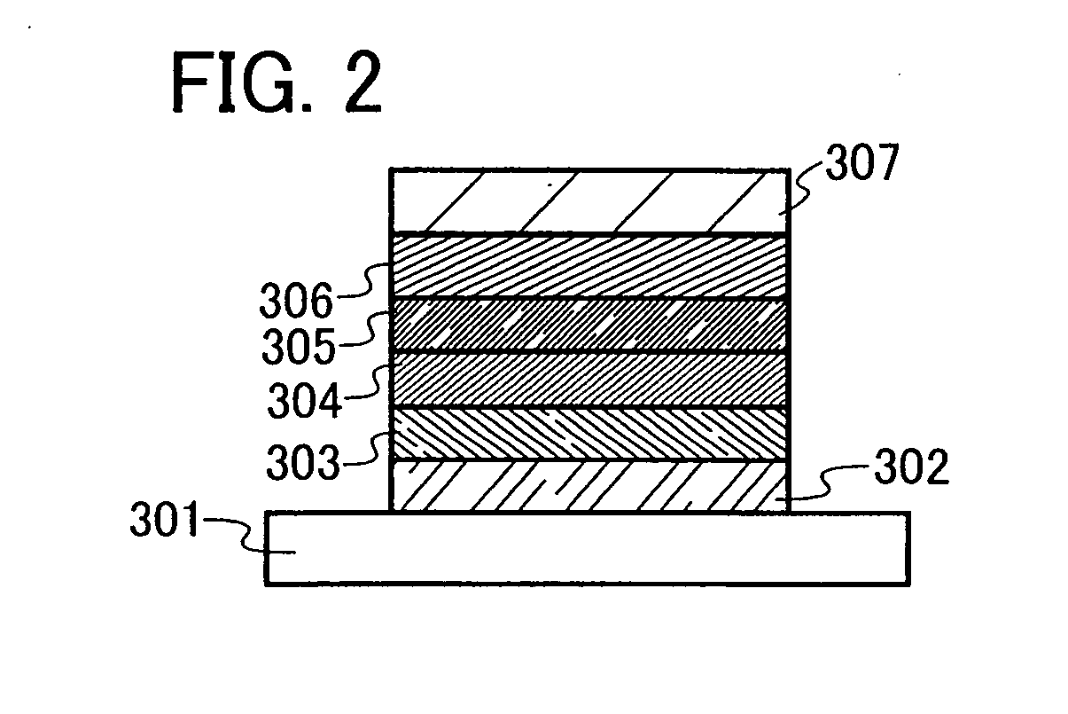
[0180] In this embodiment mode, a light-emitting element having a different structure from that described in Embodiment Mode 2 will be explained.

[0181] The third layer 105, described in Embodiment Mode 2, can be formed by dispersing the quinoxaline derivative of the present invention in another substance, by which light emission can be obtained from the quinoxaline derivative of the present invention. Since the quinoxaline derivative of the present invention exhibits emission of blue to blue green light, a blue to blue green emissive light-emitting element can be obtained.

[0182] Here, various materials can be used as a substance in which the quinoxaline derivative of the present invention is dispersed. In addition to the substance having a high hole transporting property and the substance having a high electron transporting property, which are described in Embodiment Mode 2, 4,4′-bis(N-carbazolyl)-biphenyl (abbreviation: CBP), 2,2′,2″-(1,3,5-benzenetri-yl)-tris[1-phenyl-1H-benzimi...


PUM

PropertyMeasurementUnit
thicknessaaaaaaaaaa
work functionaaaaaaaaaa

Abstract

It is an object to provide a novel bipolar organic compound. In particular, it is an object to provide a bipolar organic compound excellent in thermal stability. Further, it is another object to provide a bipolar organic compound which is electrochemically stable. A quinoxaline derivative represented by a general formula (1) is provided. Further, since the quinoxaline derivative represented by the general formula (1) is bipolar, the use of the quinoxaline derivative of the present invention allows fabrication of a light-emitting element and a light-emitting device with a low driving voltage and low power consumption. Furthermore, a light-emitting element with high luminous efficiency can be obtained.

Description

TECHNICAL FIELD [0001] The present invention relates to a quinoxaline derivative, and a light-emitting element, a light-emitting device, an electronic device each of which uses the quinoxaline derivative. BACKGROUND ART [0002] Organic compounds can take various structures compared with inorganic compounds, and have possibility to provide materials having various functions by appropriate molecular design. Owing to these advantages, photo electronics and electronics which utilize functional organic materials have been attracting attention in recent years. [0003] For example, a solar cell, a light-emitting element, an organic transistor, and the like are exemplified as an electronic device utilizing an organic compound as a functional material. These are devices taking advantage of electric properties and optical properties of the organic compound. Among them, in particular, a light-emitting element has been making remarkable development. [0004] It is considered that light emission mec...

Claims


Application Information

Patent Timeline
Patent Type & Authority Applications(United States)
IPC IPC(8): H01J1/62C07D403/02C07D241/36
CPCC07D241/12C07D241/42C07D241/44C07D403/12C07D403/14C09K11/06C09K2211/1044C09K2211/185H05B33/20H10K85/615H10K85/631H10K85/636H10K85/633H10K85/324H10K85/342H10K85/6572H10K50/11H10K2102/103
Inventor EGAWA, MASAKAZUKAWAKAMI, SACHIKONAKASHIMA, HARUEOHSAWA, NOBUHARUSEO, SATOSHINOMURA, RYOJI
Owner SEMICON ENERGY LAB CO LTD
Learn More