
Piezoelectric actuator

a technology of actuators and actuators, applied in the direction of machines/engines, inorganic chemistry, niobium compounds, etc., can solve the problems of large environmental load, low cost of drive circuits, and inability to use batiosub>3 /sub>ceramic at high temperatures, so as to reduce the temperature dependence of the displacement of the actuator to be controlled according to the constant-charge method, the effect of improving the displacement performance of the actuator

Active Publication Date: 2007-10-04
DENSO CORP
View PDF4 Cites 15 Cited by
  • Summary
  • Abstract
  • Description
  • Claims
  • Application Information

AI Technical Summary

Benefits of technology

[0053] Consequently, for improvement in the displacement performance of an actuator and the compactness and low cost of the drive circuit, the temperature dependencies of the values 1 / C0.5 and 1 / C dependent on driving electric field strength should preferably be small.
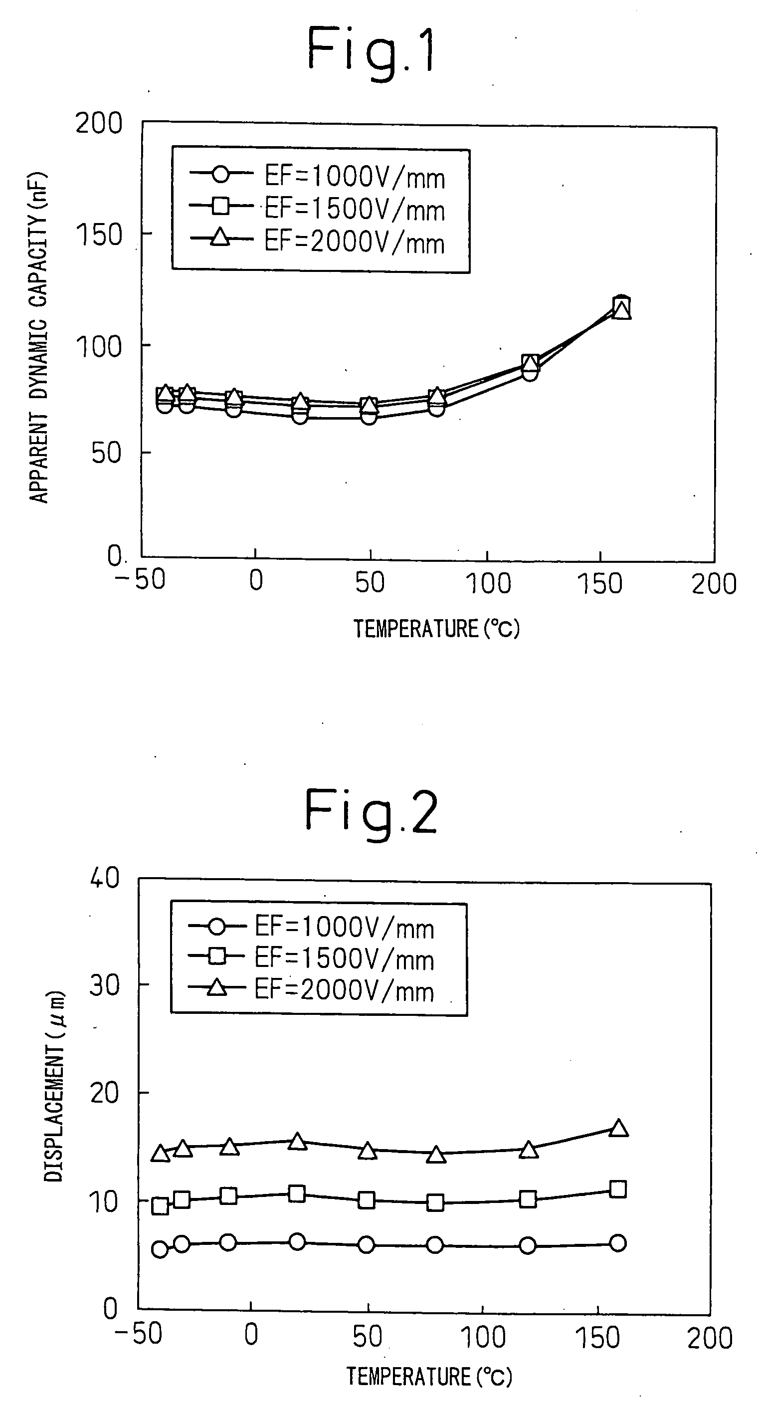
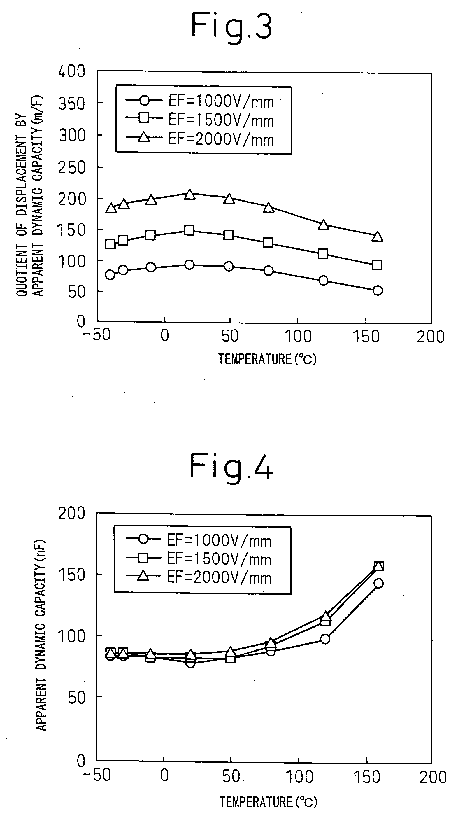
[0054] Moreover, when the apparent dynamic capacity C converges on a certain value, the terminal voltage also converges on a certain value. Therefore, if the temperature dependency of the quotient D33 / C0.5 with driving electric field strength held constant is small, the temperature dependency of a displacement of an actuator to be controlled according to the constant-energy method can be reduced. Moreover, if the temperature dependency of the quotient D33 / C with the driving electric field strength held constant is small, the temperature dependency of the displacement of the actuator to be controlled according to the constant-charge method can be reduced.

Problems solved by technology

However, as the PZT-system piezoelectric ceramics contain lead oxide exhibiting a high vapor pressure, a load they impose on an environment is large.
Moreover, as the Curie temperature of the BaTiO3 ceramic is as low as approximately 120° C., the BaTiO3 ceramic cannot be used at high temperatures.
The constant-voltage driving method has a drawback that the variation width in a displacement over a working temperature range is relatively large.
However, the conventional technologies have failed to resolve a fluctuation in the displacement characteristic of a piezoelectric actuator derived from a change in temperature.

Method used


Image

  • Piezoelectric actuator
  • Piezoelectric actuator
  • Piezoelectric actuator

Examples


example 1

[0229] Next, examples of the present invention will be described below.

[0230] In the present example, a piezoelectric element including a piezoelectric ceramic member is produced, and used to produce a piezoelectric actuator.

[0231] In the present example, a piezoelectric actuator 11 including a jig 8 is, as shown in FIG. 37, produced as a model of a piezoelectric actuator.

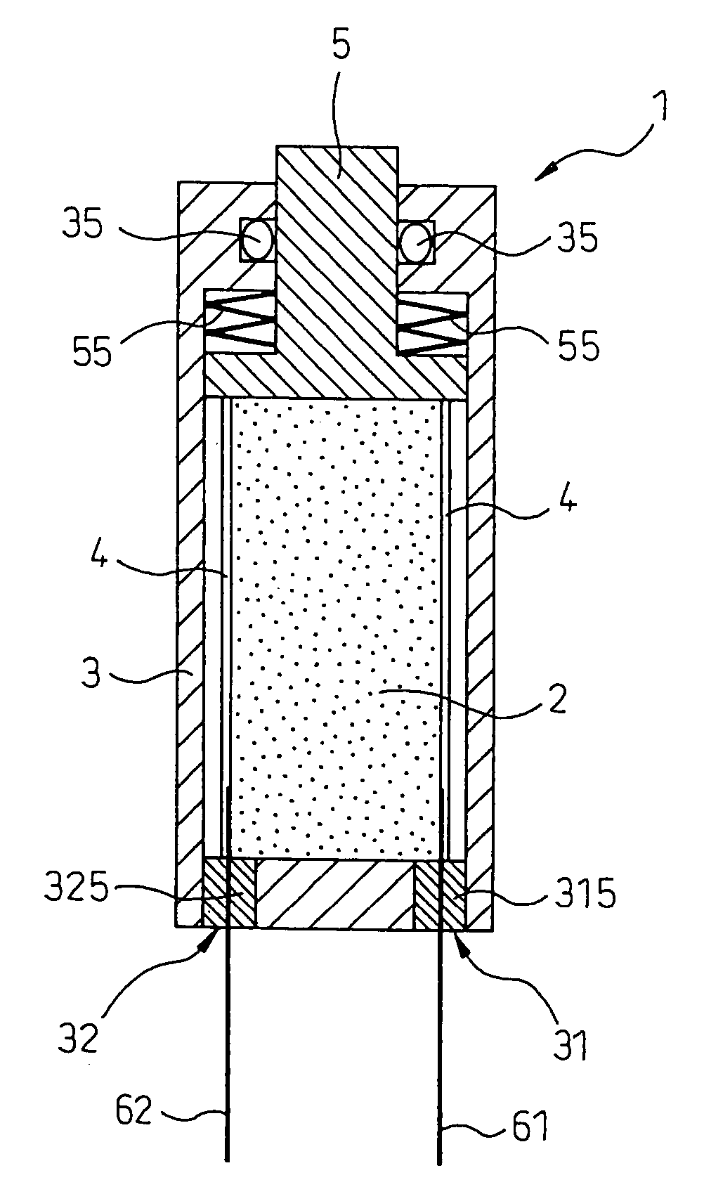
[0232] Specifically, the piezoelectric actuator 11 of the present example includes a laminated piezoelectric element 2 using a sheet of piezoelectric ceramic as a drive source, and has the piezoelectric element 2 locked in the jig 8.

[0233] The jig 8 includes a housing 81 that accommodates the piezoelectric element 2 and a piston (coupling member) 82 that is coupled to the piezoelectric element 2 and conveys a displacement made by the piezoelectric element 2. The piston 82 is coupled to a guide 83 via a disk spring 85. A pedestal portion 815 is formed in the housing 31, and the piezoelectric element 2 is placed ...

example 2

[0281] A crystal-oriented ceramic having the composition of {Li0.07(K0.45Na0.55)0.93}{Nb0.82Ta0.10Sb0.08}O3 was produced according to the same procedure as the one employed in Example 1 except that the firing temperature for a degreased plate-like compact was set to 1105° C. The produced crystal-oriented ceramic was evaluated in terms of the density of a sintered compact, an average orientation degree, and piezoelectric properties under the same conditions as those defined in Example 1. Moreover, a laminated actuator including forty sheets of piezoelectric ceramic was produced according to the same procedure as that employed in Example 1, and the characteristics of the actuator were evaluated.

[0282] The relative density of the crystal-oriented ceramic produced in the present example was 95% or more. Moreover, the pseudo-cubic {100} planes were oriented in parallel to the tape surface. The average orientation degree of the pseudo-cubic {100} planes calculated according to the Lotger...

example 3

[0296] A crystal-oriented ceramic having the composition of {Li0.065(K0.45Na0.55)0.935}{Nb0.83Ta0.09Sb0.08}O3 was produced according to the same procedure as the one employed in Example 1 except that the firing temperature for a degreased plate-like compact was set to 1105° C. The produced crystal-oriented ceramic was evaluated in terms of the density of a sintered body, an average orientation degree, and piezoelectric properties under the same conditions as those specified in Example 1. Moreover, a laminated actuator including forty sheets of piezoelectric ceramic was produced according to the same procedure as that employed in Example 1, and the characteristics of the actuator were evaluated.

[0297] The relative density of the crystal-oriented ceramic of the present example was 95% or more. Moreover, the pseudo-cubic {100} planes were oriented in parallel with the tape surface, and the average orientation degree of the pseudo-cubic {100} planes calculated according to the Lotgerin...


PUM

PropertyMeasurementUnit
electric field strengthaaaaaaaaaa
temperatureaaaaaaaaaa
temperaturesaaaaaaaaaa

Abstract

A piezoelectric actuator 1 includes a piezoelectric element 2, which has a pair of electrodes formed on the surface of a piezoelectric ceramic member, as a drive source. The piezoelectric actuator 1 satisfies at least one of the following requirements (a) to (c): (a) the variation width WC in an apparent dynamic capacity C [F] due to a change in temperature should fall within ±11% over a specific temperature range from −30° C. to 80° C.; (b) the variation width WL in a displacement L [μm] due to a change in temperature should fall within ±14% over the specific temperature range from −30° C. to 80° C.; and (c) the variation width WL / C in a quotient L / C due to a change in temperature should fall within ±12% over the specific temperature range from −30° C. to 80° C., wherein C [F] denotes the apparent dynamic capacity and L [μm] denotes the displacement.

Description

CROSS-REFERENCE TO RELATED APPLICATIONS [0001] This application is based upon and claims priority of Japanese Patent Applications No. 2004-266110, filed on Sep. 13, 2004, and No. 2005-228396, filed on Aug. 5, 2005, the contents being incorporated herein by reference, and a continuation of PCT / JP2005 / 017231.BACKGROUND OF THE INVENTION [0002] 1. Field of the Invention [0003] The present invention relates to a piezoelectric actuator, utilizing a reverse piezoelectric effect and an electrostrictive effect under the influence of a large electric field, such as; a laminated actuator, a piezoelectric transformer, an ultrasonic motor, a bimorph piezoelectric element, an ultrasonic sonar, a piezoelectric ultrasonic vibration element, a piezoelectric buzzer, or a piezoelectric loudspeaker. [0004] 2. Description of the Related Art [0005] Piezoelectric actuators employing piezoelectric ceramic materials are industrial products that convert electric energy into mechanical energy by utilizing dis...

Claims


Application Information

Patent Timeline
Patent Type & Authority Applications(United States)
IPC IPC(8): H01L41/00F02M51/06H01L41/083H01L41/09H01L41/187
CPCC01G33/006H01L41/1873C01P2002/52C01P2006/32C01P2006/40C01P2006/42C04B35/493C04B35/495C04B35/645C04B2235/3201C04B2235/3203C04B2235/3213C04B2235/3225C04B2235/3251C04B2235/3255C04B2235/3262C04B2235/3294C04B2235/3298C04B2235/444C04B2235/5292C04B2235/5296C04B2235/5436C04B2235/5445C04B2235/604C04B2235/656C04B2235/6562C04B2235/6565C04B2235/6585C04B2235/762C04B2235/768C04B2235/77C04B2235/787C04B2235/9623H01L41/0833C01G35/006H10N30/503H10N30/8542
Inventor NAGAYA, TOSHIATSUNONOYAMA, TATSUHIKONAKAMURA, MASAYASAITO, YASUYOSHITAKAO, HISAAKIHOMMA, TAKAHIKOTAKATORI, KAZUMASA
Owner DENSO CORP
Learn More