

Reinforced composite electrolyte membrane for fuel cell
a fuel cell and electrolyte membrane technology, applied in the direction of non-aqueous electrolyte cells, cell components, sustainable manufacturing/processing, etc., can solve the problems of degradation of the quality of the fuel cell, drop in efficiency of the polymer membrane at a temperature of 80° c. or higher, and undesired drop in the ion conductivity of the membrane, so as to achieve excellent durability and improve the effect of quality
- Summary
- Abstract
- Description
- Claims
- Application Information
AI Technical Summary
Benefits of technology
Problems solved by technology
Method used
Image

Examples
example 1
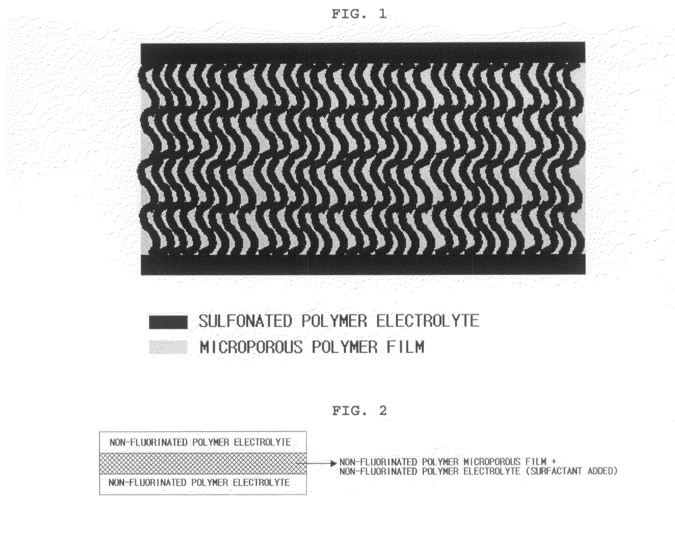
Manufacture of Reinforced Composite Electrolyte Membrane Using First and Third Polymer Electrolyte Solutions Containing no Surfactant, Second Polymer Electrolyte Solution Containing Surfactant, and a Non-Fluorinated Microporous Polymer Substrate
[0058]First, 10 g of a sulfonated poly(ether ketone) block copolymer, prepared according to examples disclosed in Korean Patent Application No. 10-2004-0110487, was dissolved in 90 g of dimethyl formamide (DMF), and the resultant solution was filtered through a BORU glass filter (pore size 3) to remove dust, etc. Next, 30 g of the above solution was separately used to form a second polymer solution to which 4% of Triton X-100 (a surfactant) was added. The remaining 70 g of the solution was used to provide a first polymer solution and a third polymer solution. Then, a polyethylene-based microporous film was washed with ethanol, followed by drying. The first polymer solution was poured onto a glass base and the copolymer solution applied onto t...
example 2
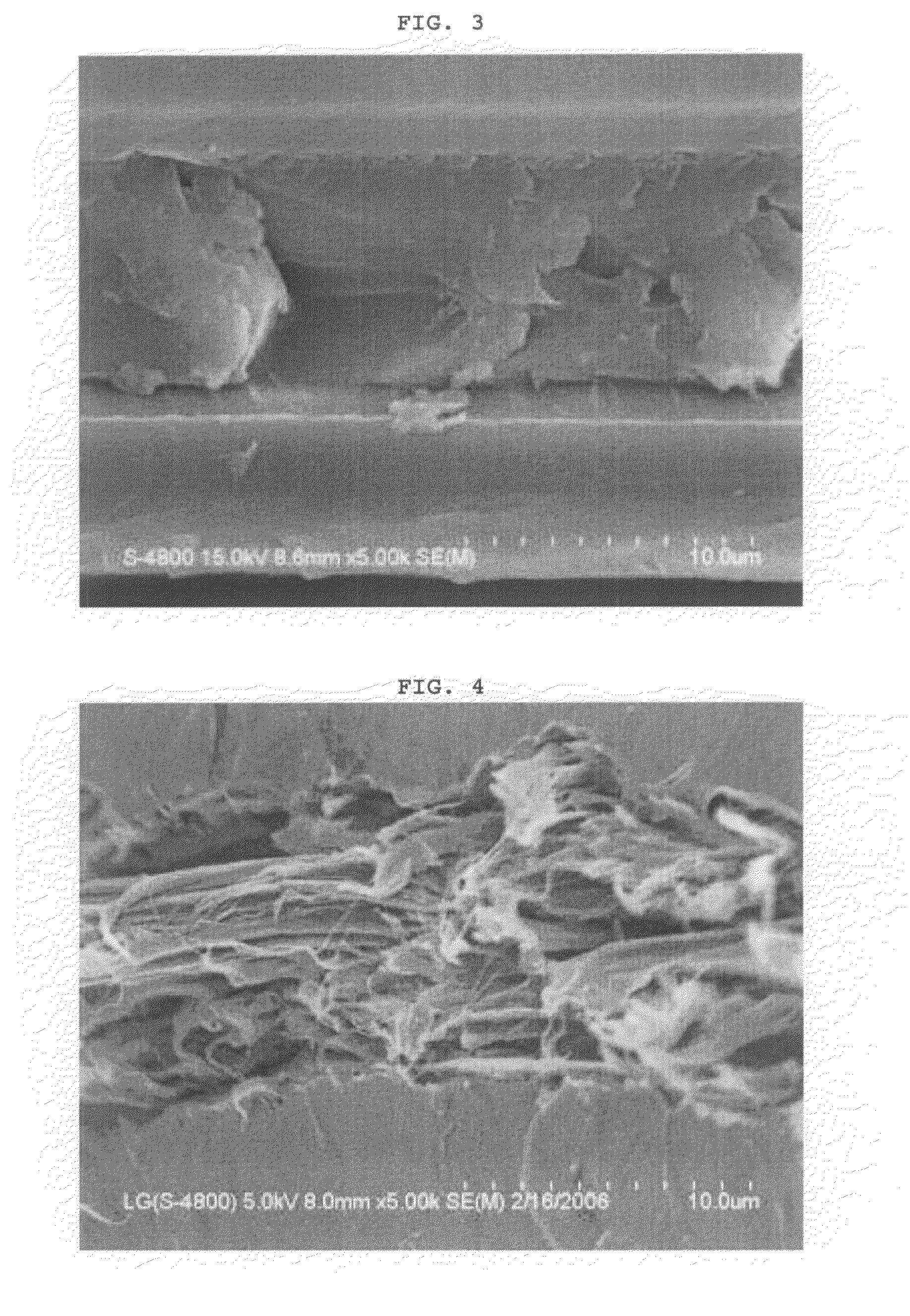
[0060]Manufacture of reinforced composite electrolyte membrane using no surfactant in first, second and third polymer electrolyte solutions and using a non-fluorinated microporous polymer substrate
[0061]An electrolyte membrane having a thickness of 50 μm was provided in the same manner as described in Example 1, except that the same sulfonated poly(ether ketone) block copolymer solution was used as the first polymer solution, the second polymer solution and as the third polymer solution (i.e. the second polymer solution contained no surfactant). FIG. 4 is the sectional image of the reinforced composite electrolyte membrane obtained as described above, taken by SEM.
example 3
Manufacture of Reinforced Composite Electrolyte Membrane Using First and Third Polymer Electrolyte Solutions Containing no Surfactant, Second Polymer Electrolyte Solution Containing Surfactant, and a Partially-Fluorinated Microporous Polymer Substrate
[0063]An electrolyte membrane having a thickness of 50 μm was provided in the same manner as described in Example 1 except that a polyvinyldifluoroethylene microporous membrane, which is a partially-fluorinated microporous membrane, was used instead of a polyethylene microporous membrane, which is a non-fluorinated microporous membrane, and that fluorinated surfactant was used instead of the surfactant used in Example 1, i.e., Triton X-100 in order to increase the affinity between the microporous membrane and the sulfonated poly (ether ketons) block copolymer solution used in Example 1.
PUM
| Property | Measurement | Unit |
|---|---|---|
| temperature | aaaaa | aaaaa |
| pore size | aaaaa | aaaaa |
| porosity | aaaaa | aaaaa |
Abstract
Description
Claims
Application Information