Method and system for liquid and vapor leak detection

a liquid and vapor leak detection and detection method technology, applied in the direction of fluid tightness measurement, digital computer details, instruments, etc., can solve the problems of vapor emissions affecting the economic loss of the retailer, environmental hazards to both air and groundwater, and negative impact on human health

Inactive Publication Date: 2007-10-18
ARID TECH
View PDF3 Cites 4 Cited by
  • Summary
  • Abstract
  • Description
  • Claims
  • Application Information

AI Technical Summary

Benefits of technology

[0016] The present invention provides a simple means to calculate the vapor generation rate within the storage tanks. The vapor generation rate can easily be converted into a mass emission rate and / or an equivalent loss rate of liquid fuel.

Problems solved by technology

These gasoline vapor emissions represent an economic loss to the retailer, an environmental hazard to both air and groundwater and a negative impact on human health since benzene is a known human carcinogen.
Accordingly, vapor losses from fixed-roof gasoline storage tanks includes displacement losses caused by inflow of liquid, breathing losses caused by temperature and atmospheric pressure variations, and emptying losses caused by evaporation of liquid after the transfer of product occurring during the interval between the next product delivery
The high tank pressures result in “below grade vapor emissions” which eventually condense and find their way into groundwater.
The problems in Maryland were amplified by two high profile release incidents where large volumes of liquid phase gasoline were leaked from fueling stations into groundwater which comprised residential drinking wells for nearby residents.
However, upon closer examination, the existing products and services have significant disadvantages.
If the owner or operator of a gasoline refueling station is confident that liquid leaks are not present, the other means of apparent or measured loss of mass are through evaporation loss, meter miscalibration, invoice errors, theft or volumetric changes due to temperature variation.
The first error caused by a change in specific volume (density) of the fluid being measured causes the float used in magnetostrictive probes to register an inaccurate reading.
A small error of only 0.10 inches of height will yield a corresponding error of 13.5 gallons of liquid volume in just a single tank.
The second error caused by the temperature and density variation of fuel results in an inaccurate and non-repeatable measurement of dispensed fuel.
Dispenser meters in the United States are not temperature compensated such as those in other countries such as Canada.
Unless these temperatures are exactly the same, the raw data inputs will be comprised of poor quality data.
No matter how sophisticated the algorithms are within the various vendor supplied packages for inventory reconciliation and leak detection, the results are doomed to failure based on poor quality raw data inputs.
Perhaps if gasoline was used as the test fluid, many of the systems and / or algorithms receiving commercial approval at very low detection limits would be found inappropriate.
Perhaps the various inventory control systems provide a business management tool, but reliance on existing algorithms for detailed leak detection and regulatory compliance does not seem to be a wise choice.
These systems are complicated and costly to retrofit to existing fueling stations.
However, the installation of such flow meters at a large number of refueling sites is not practical, and another simpler means is required to readily calculate the vapor generation rates within the storage tanks over a wide range of conditions.
Also, the mere installation of the flow meter device itself represents additional leak sources within the vapor piping at the refueling facility.

Method used


Image

  • Method and system for liquid and vapor leak detection
  • Method and system for liquid and vapor leak detection
  • Method and system for liquid and vapor leak detection

Examples


Embodiment Construction

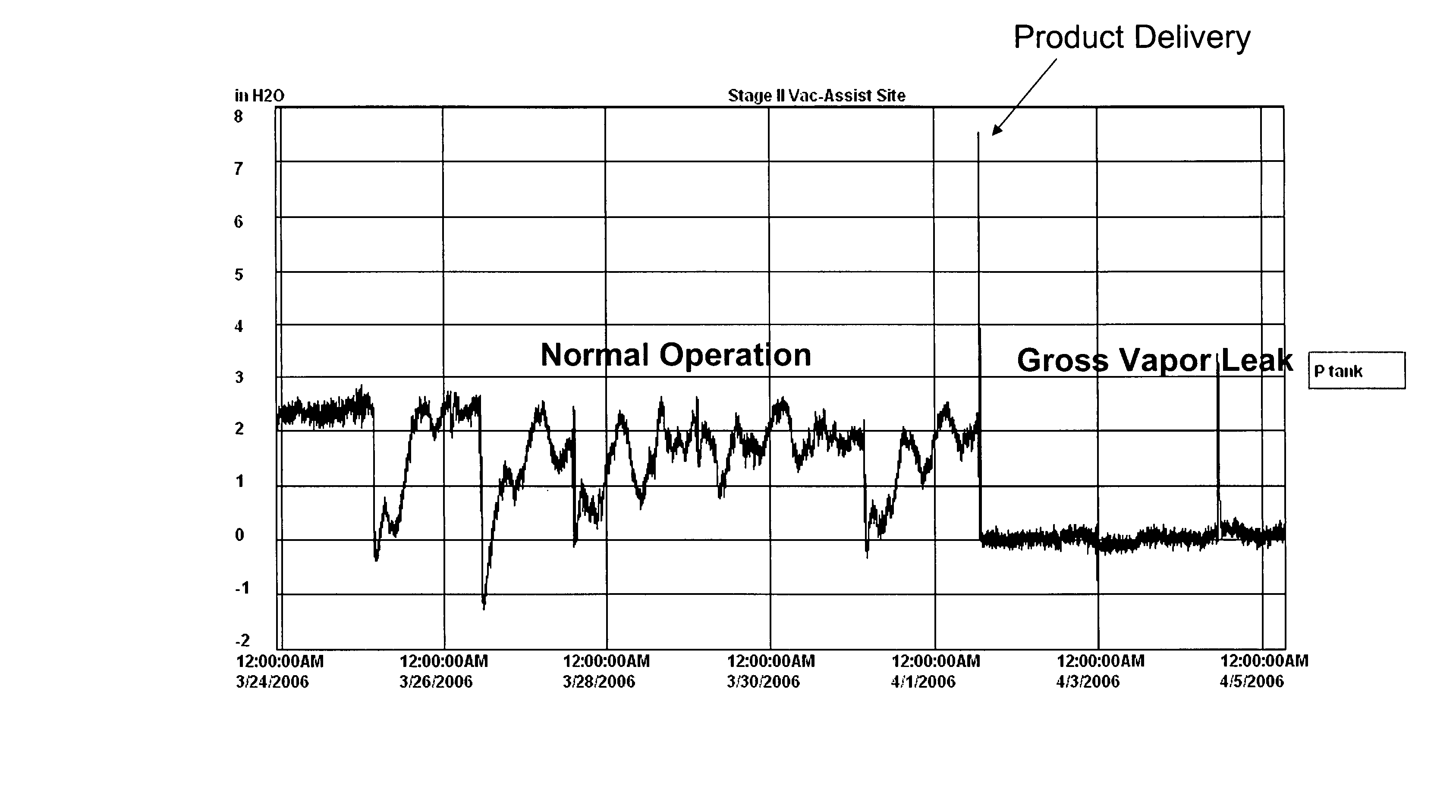
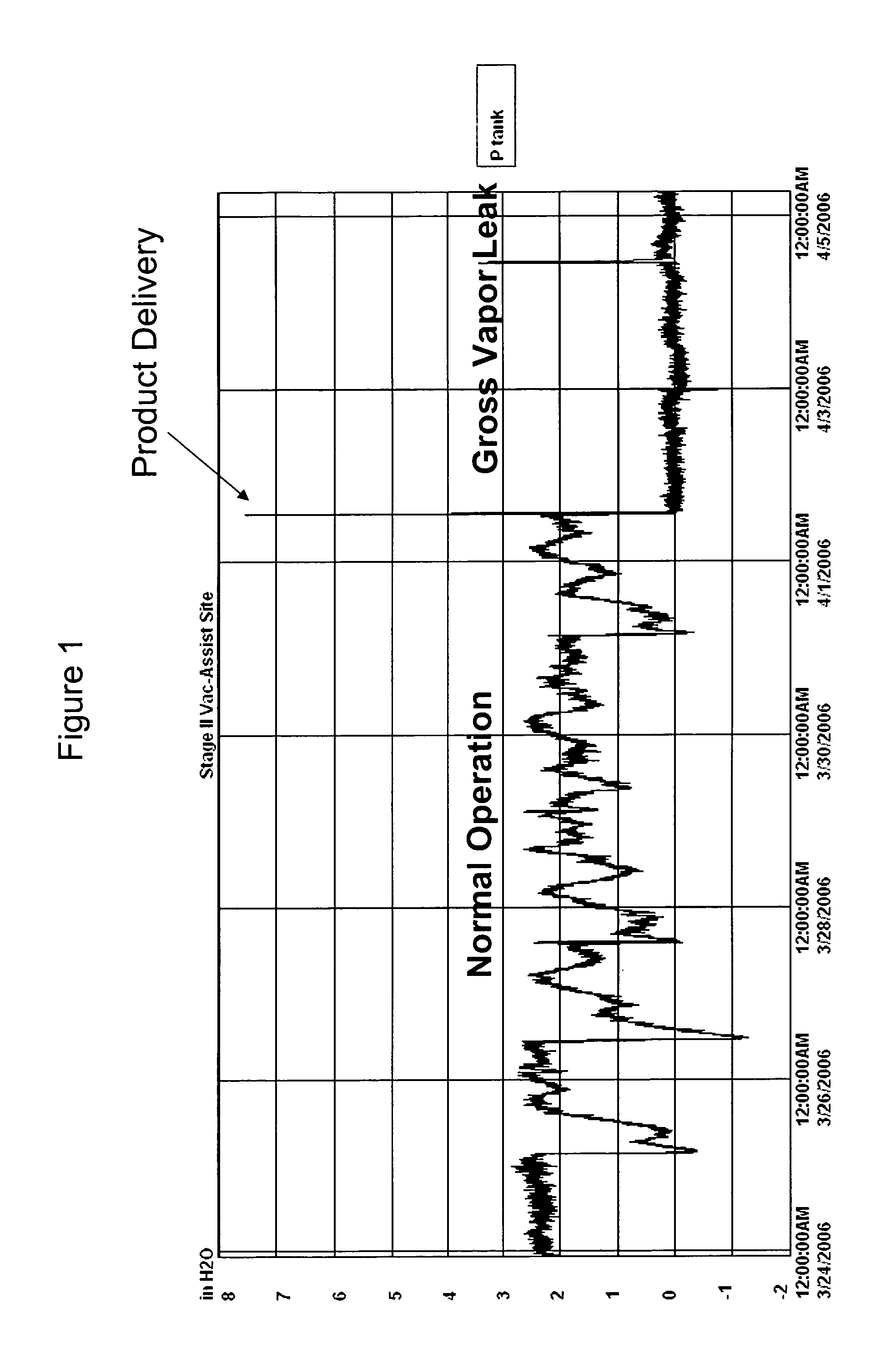
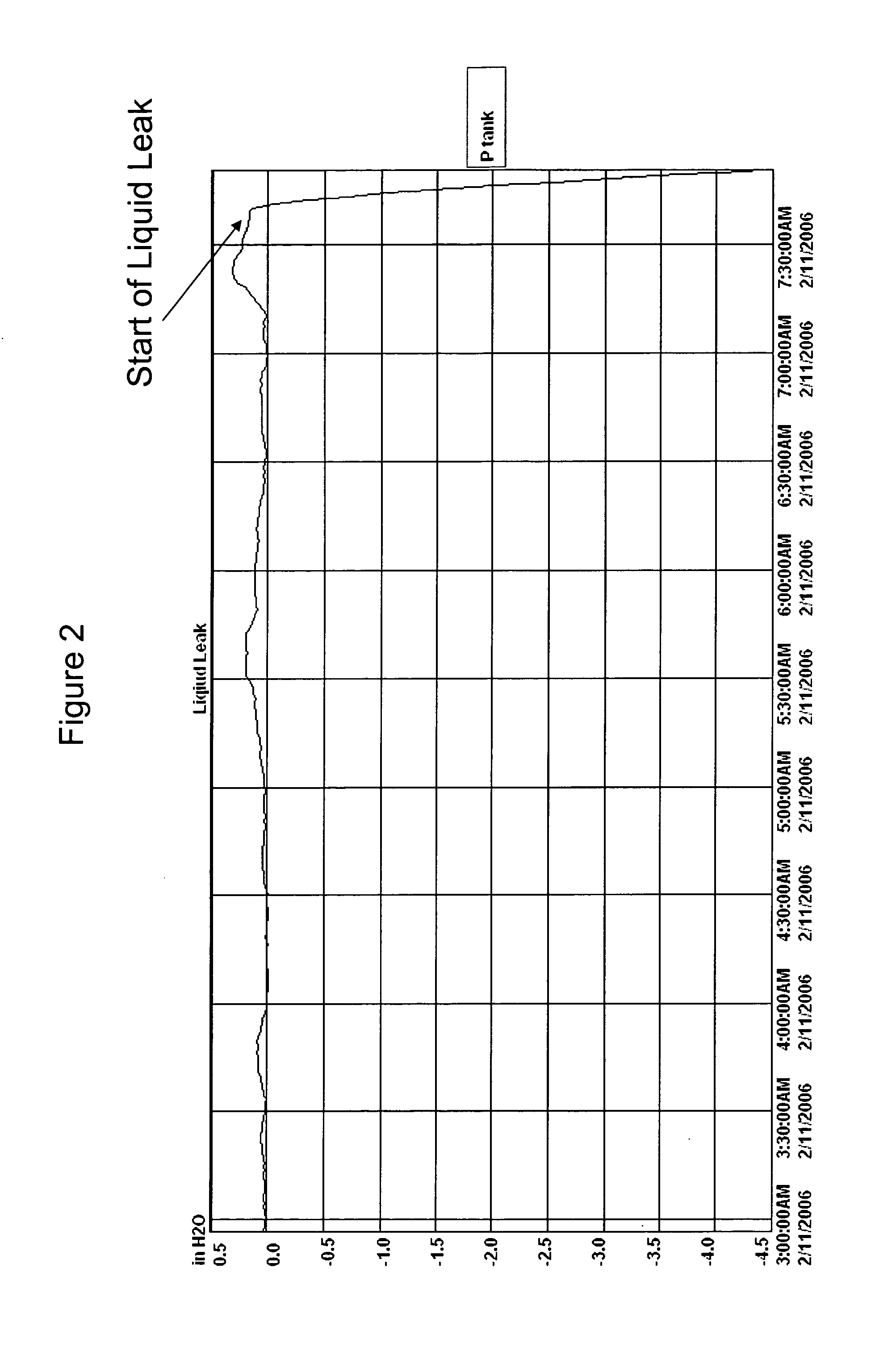
[0023] The present invention comprises a method of transforming an “open” gasoline storage and transfer system to a “closed” system. The method includes providing a selectively permeable membrane processor on the combined storage tank ullage space in conjunction with the installation of a p / v valve on the combined storage tank vent lines. The normal vent to atmosphere is fitted with the p / v valve such that the storage tank system becomes a closed system, sealed off from the atmosphere. A pressure sensor is installed to measure atmospheric pressure and another sensor is installed to measure and monitor the pressure differential between the combined storage tank ullage and prevailing atmospheric pressure. When the pressure differential reaches a prescribed value, the membrane processor is actuated to exhaust to the atmosphere air which has been depleted of hydrocarbons and return vapors, enriched with hydrocarbons to the combined ullage space. (See U.S. Pat. No. 6,836,732 B2)

[0024] I...


PUM


Abstract

The present invention relates generally to the commercial distribution and sales of volatile motor fuels and more specifically to systems and methods for ensuring leak free storage of both liquid and vapor phase states of fuels stored at dispensing facilities. In addition, the present invention presents a simple means for measuring evaporative loss rates from fuel storage systems. Moreover, this invention provides a means for determining proper functioning of Stage I and Stage II vapor recovery techniques.

Description

FIELD OF THE INVENTION [0001] The present invention relates generally to the commercial distribution and sales of volatile motor fuels and more specifically to systems and methods for ensuring leak free storage of both liquid and vapor phase states of fuels stored at dispensing facilities. In addition, the present invention presents a simple means for measuring evaporative loss rates from fuel storage systems. Moreover, this invention provides a means for determining proper functioning of Stage I and Stage II vapor recovery techniques. BACKGROUND OF THE INVENTION [0002] Various stationary and mobile tanks are used in the production, storage and distribution of volatile organic compounds such as fuels, solvents and chemical feedstocks. When transferring a volatile fuel such as gasoline from a fixed roof storage tank to a fixed roof receiving tank; two events simultaneously occur. Vapors in the receiving tank ullage (space above the liquid) are displaced by the incoming liquid, and a ...

Claims


Application Information

Patent Timeline
Patent Type & Authority Applications(United States)
IPC IPC(8): G01M3/08
CPCG01M3/2892
Inventor TIBERI, TEDMUND P.
Owner ARID TECH
Why Eureka
Try Eureka