Active temperature feedback control of continuous casting

a continuous casting and feedback technology, applied in the direction of instruments, instruments, optical radiation measurement, etc., can solve the problems of limited control of temperature, inability to integrate the temperature, and inability to accurately control the temperature, so as to achieve uniform surface temperature

Inactive Publication Date: 2007-11-01
ROSEMOUNT AEROSPACE +1
View PDF22 Cites 25 Cited by
  • Summary
  • Abstract
  • Description
  • Claims
  • Application Information

AI Technical Summary

Benefits of technology

[0017]In accordance with a further aspect of the invention, the program further comprises means for providing individualized control of each of a plurality of nozzles or banks of nozzles through which cooling fluid is directed inside of the caster. The program may also include means for maintaining a substantially uniform surface temperature across the surface of the stream of material while it solidifies. Moreover, the program can also include means for sensing when a molten core of the stream of material breaks out through a

Problems solved by technology

Unfortunately because of the design of modern continuous casting machines, limited control of temperature is possible.
However, no successful attempts have been made to integrate that temperature to a predetermined curve such as an ideal curve, and imprecise cooling is the result.
Breakout is a major problem.
Breakout occurs when the thin shell of the strand of material breaks, allowing the still-molten metal inside the strand to spill out and foul the casting system, requiring an expensive shutdown.
Often, breakout is due to too high a withdrawal rate, as the shell has not had the time to solidify to the required thickness, or the metal is too hot, which means that final solidification takes place below the straightening rolls and the strand breaks due to stresses applied during straightening.
Either of these failures results in costly further processing, waste, or expensive and d

Method used


Image

  • Active temperature feedback control of continuous casting
  • Active temperature feedback control of continuous casting
  • Active temperature feedback control of continuous casting

Examples


example

Testing of In Situ UV Pyrometer and Two-Color Pyrometer

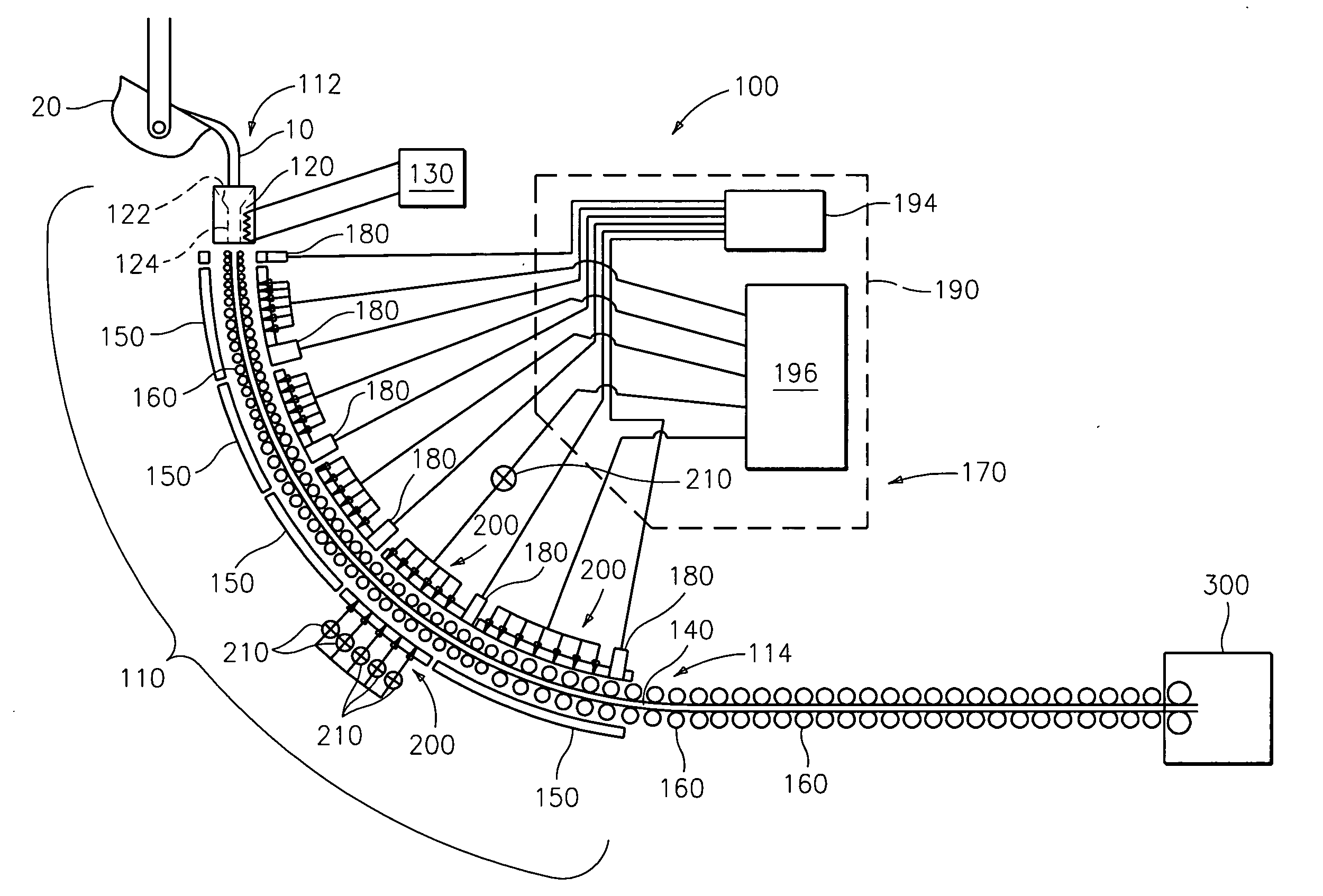
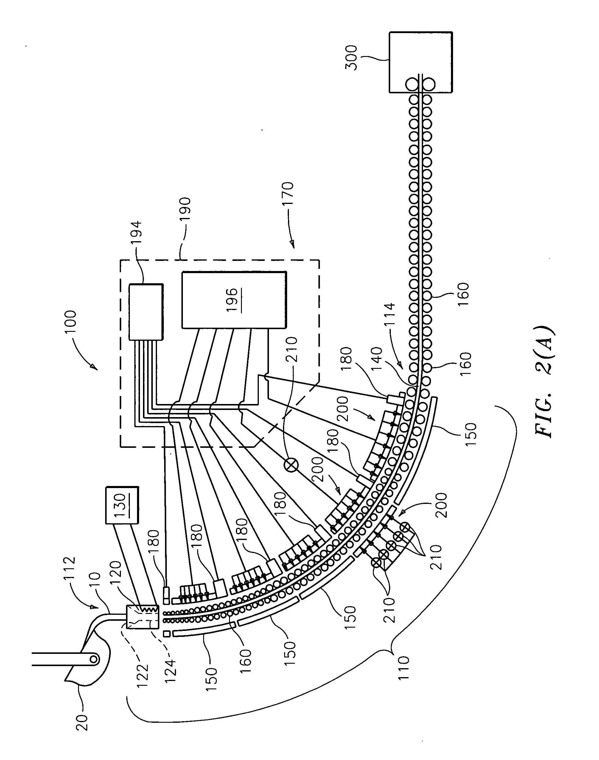
[0073]Testing was performed at a steel mill during a continuous casting process. The test employed a temperature sensor similar to sensor 1800 described above including a UV pyrometer to measure the steel temperature. A NIR (near infrared) pyrometer was also mounted at the same location with a tubular member having a gas purge as described herein. Data was examined to compare the accuracy of the spectra obtained from the two pyrometers.

[0074]The UV pyrometer utilized silicon photodiodes as photon sensors. Two of the photodiodes were filtered with a color glass filter. This provided a useable spectrum of about 350 nm to 450 nm, well overlapping the UV portion of the electromagnetic spectrum. The NIR pyrometer was a Goodrich production model modified to include a purge line. The NIR pyrometer uses a silicon photodiode that is not filtered. It has a standard silicon responsivity with a peak sensitivity at about 850 nm.
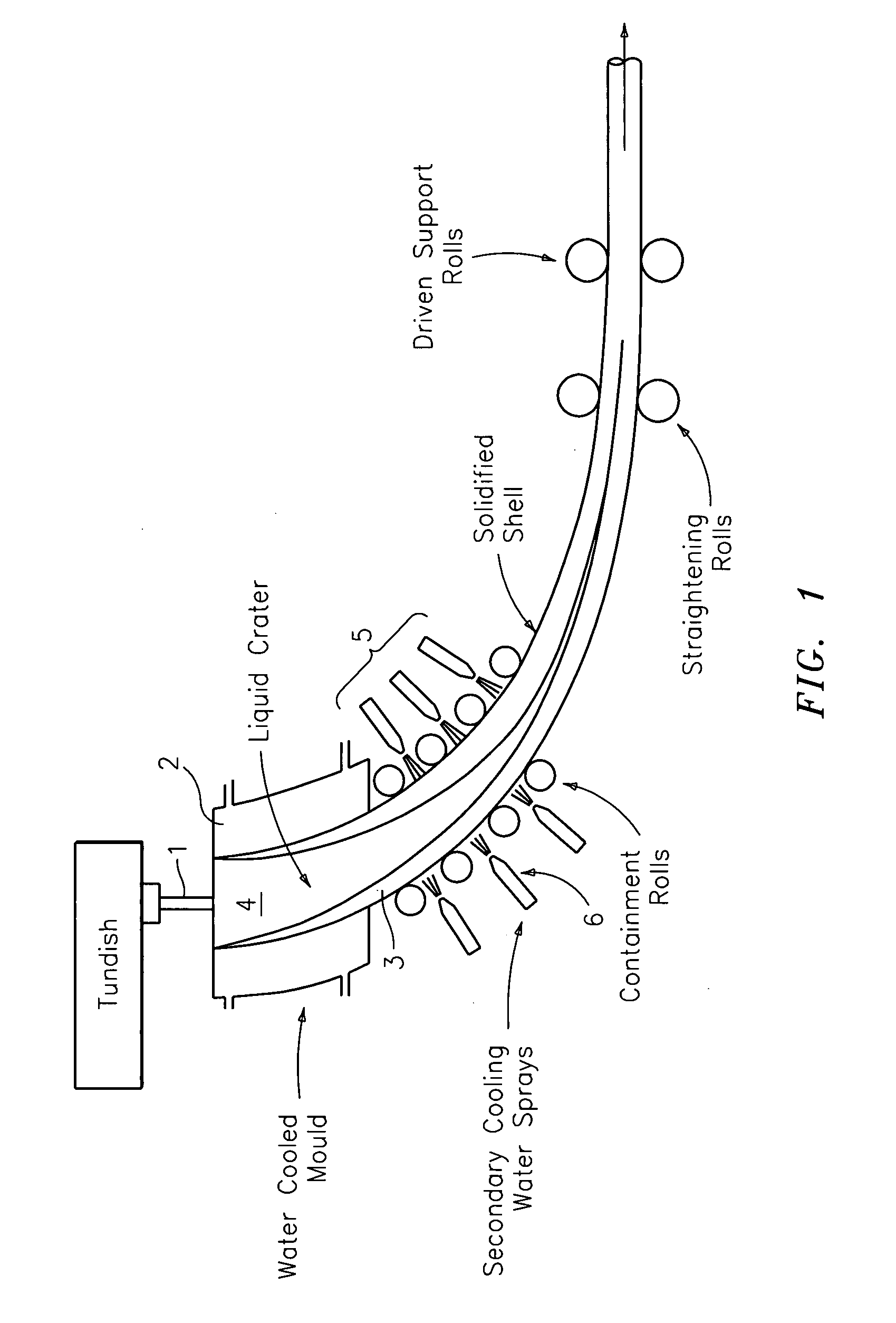
[0075]FIG. 1...


PUM

PropertyMeasurementUnit
Wavelengthaaaaaaaaaa
Temperatureaaaaaaaaaa
Lengthaaaaaaaaaa

Abstract

The invention includes a system, method and machine readable program for dynamically controlling the casting of a material. Generally, the systems and methods described herein include an active control feedback system or aspects thereof including a temperature sensing device that is well-suited for the harsh environment of the interior of a caster such as a caster for casting metal. Temperature measurement can be accomplished either directly or indirectly. The system is configured to compare the measured temperature with an ideal casting temperature. The temperature sensing device is operably coupled to a cooling device that modulates a flow of coolant to dynamically cool the material being cast. In accordance with one embodiment of the invention, the cooling device includes a plurality of nozzles for delivering one or more cooling fluids to the material being cast.

Description

CROSS-REFERENCE TO RELATED APPLICATIONS[0001]This application claims the benefit of priority of U.S. Provisional Application Ser. No. 60 / 796,074 filed Apr. 28, 2006. This application is related to U.S. patent application Ser. No. 11 / 709,070 filed Feb. 21, 2007. Each of these applications is incorporated by reference herein in its entirety.BACKGROUND OF THE INVENTION[0002]1. Field of the Invention[0003]The present invention relates to continuous casting machines and particularly to the control of the secondary cooling in the continuous casting machines where molten metal is molded into cast slabs, strands, billets and the like.[0004]2. Description of Related Art[0005]In a continuous casting machine (or “caster”) as depicted in FIG. 1, molten metal 1 is poured into a cooled copper faced mold 2 which controls the physical width and thickness of the finished product. Metal exits the mold 2 in the form of a strand or slab having a thin shell 3 of solidified metal with a core 4 of molten ...

Claims


Application Information

Patent Timeline
IPC IPC(8): B22D11/22B22D11/124
CPCB22D11/225G05D23/2723G01J5/0014G01J5/0022G01J5/02G01J5/0205G01J5/0215G01J5/029G01J5/041G01J5/048G01J5/08G01J5/0806G01J5/0818G01J5/0821G01J5/601G01K13/08G05D23/2226G01J5/0003G01J5/004G05D23/22G05D23/27G05D23/1928G01J5/051
Inventor SHELDON, WILLIAMSIDERS, RANDALL DUANEMYHRE, DOUGLASLENERTZ, STEVENGRIFFITH, TIMOTHYPERCIVAL, DAVID R.
Owner ROSEMOUNT AEROSPACE
Why Eureka
Try Eureka