
Composite adsorbent block for the treatment of contaminated fluids

a technology of contaminated fluids and adsorbent blocks, which is applied in the direction of filtration separation, separation process, and treatment water nature, etc., can solve the problems of heavy metal removal, lack of stability of metal-laden products, and inconvenient water treatment technology

Inactive Publication Date: 2007-11-08
PECOFACET US
View PDF6 Cites 15 Cited by
  • Summary
  • Abstract
  • Description
  • Claims
  • Application Information

AI Technical Summary

Benefits of technology

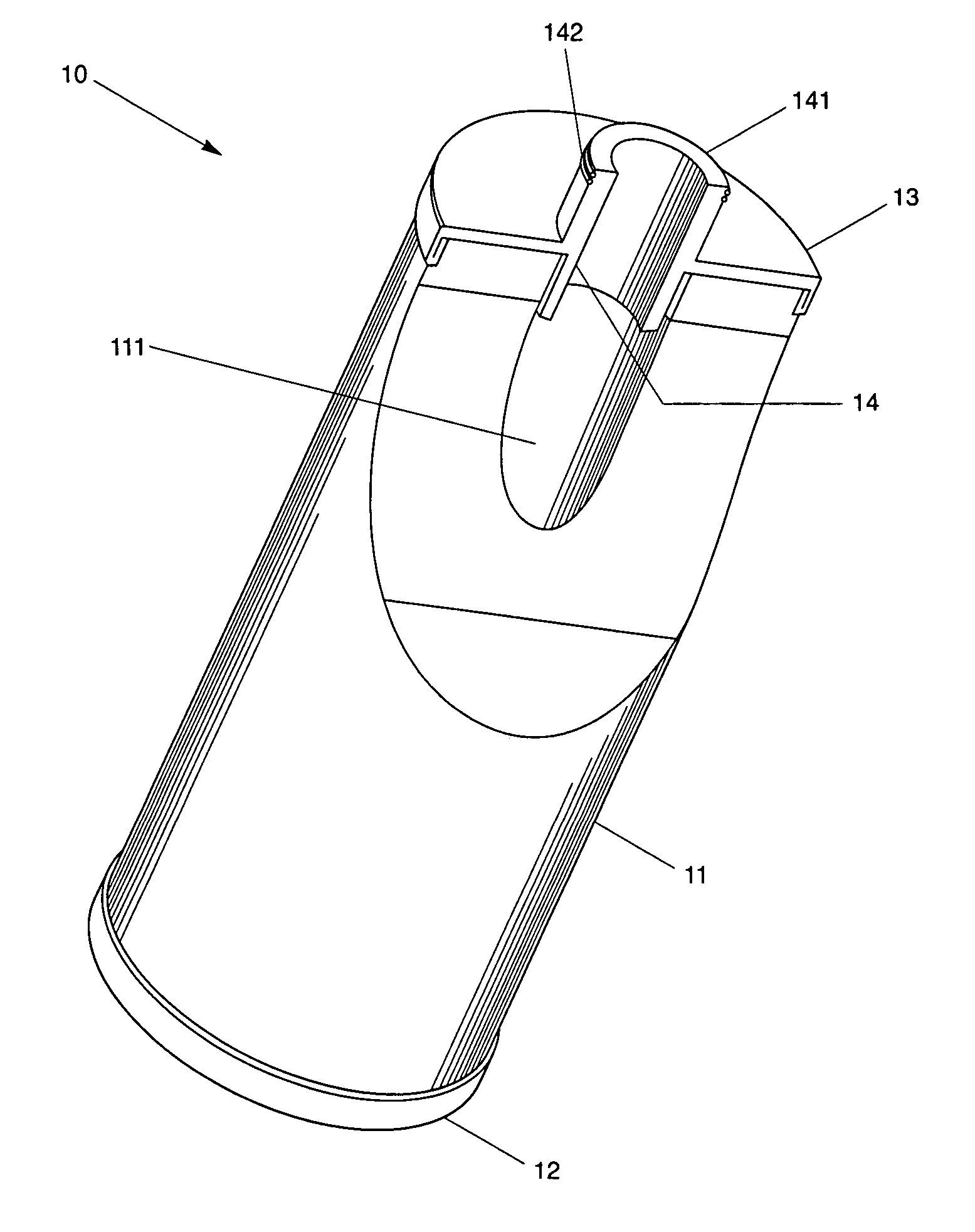
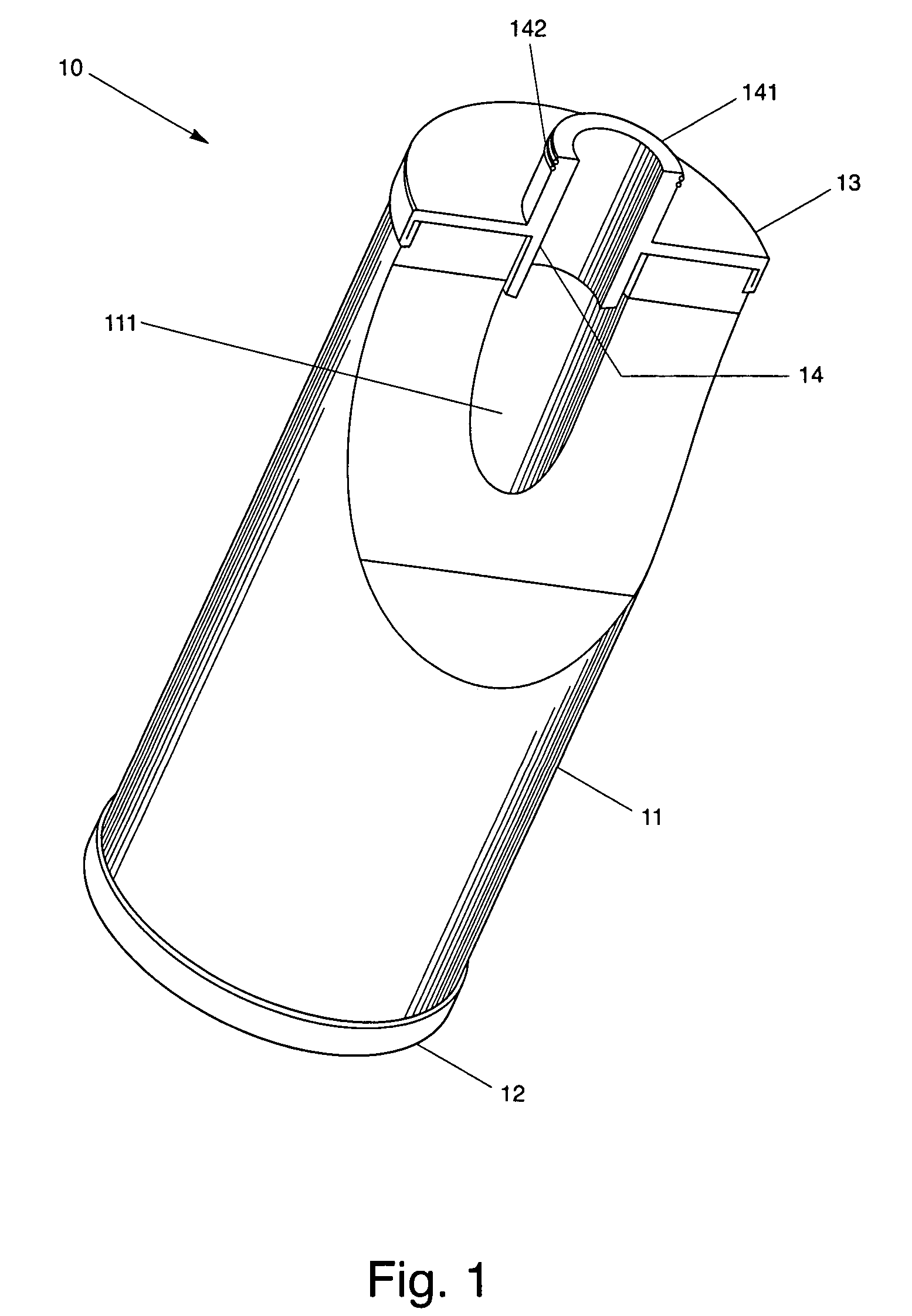
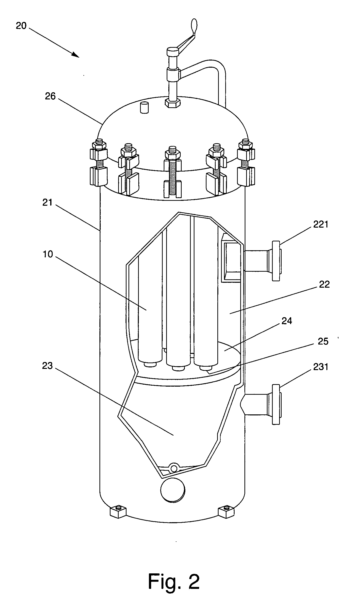
[0015] The present invention, in one embodiment, provides an apparatus for use in the treatment of contaminated fluid. The apparatus, in an embodiment, includes a body portion, made from a mixture of a waste adsorbent material and a binder material, for use in the removal of contaminants. The adsorbent material may be a nanosorbent material manufactured from self-assembled monolayers on mesoporous supports (SAMMS). The binder material, on the other hand, may include any thermoplastic material capable of binding the adsorbent material together to subsequently provide a composite material that can be shaped into a block. The apparatus may also be provided with an upper end cap placed over a top end of the body portion. An opposing lower end cap may similarly be placed over a bottom end of the body portion. The lower end cap, however, may include an aperture in axial alignment with a pathway provide along an axis of the body portion to permit treated fluid to exit the apparatus. To assist in the removal solid waste / contaminants, so that the body portion can remain substantially porous to fluid flow for an extended period, in one embodiment, an outer element substantially tubular in shape for initially removing the solid contaminants can be provided substantially circumferentially about the block.

Problems solved by technology

The presence of a complex mix of constituents coupled with a high concentration of dissolved salts can present a challenge for heavy metal removal using currently available conventional technologies.
These technologies may not suitable for water treatment because of poor metal loading (e.g., metal uptake less than 20% of the mass of the adsorber material) and selectivity, (interference from other abundant ions in groundwater).
Furthermore, they lack stability for metal-laden products so that they are not disposable directly as a permanent waste form.
Mercury removal from non-aqueous sludge, adsorbed liquids, or partially- or fully-stabilized sludges, and mercury-contaminated soil is difficult because (1) the non-aqueous nature of some wastes prevents the easy access of leaching agents, (2) some waste streams with large volumes make the thermal desorption process expensive, and (3) the treatment of some waste streams are technically difficult because of the nature of the wastes.
However, the carbon-based adsorbents are only effective enough to remove 75 to 99.9% of the mercury with a loading capacity equivalent to 1-20% of the mass of the adsorber material.
As a result, the adsorbed mercury needs secondary stabilization because the mercury-laden carbon does not have the desired long-term chemical durability due to the weak bonding between the mercury and active carbon.
However, it involves multiple steps of extraction, stripping, demulsification, and recovery of mercury by electrolysis and uses large volumes of organic solvents.
The liquid membrane swelling has a negative impact on extraction efficiency.
The slow kinetics of the metal-ion exchanger reaction requires long contacting times. This process also generates large volumes of organic secondary wastes.
Oxidation of the resin results in substantially reduced resin life and an inability to reduce the mercury level to below the permitted level of less than about 0.1 ppb.
The mercury loading is also limited because the high binding capacity of most soils to mercury cations makes the ion-exchange process ineffective, especially when the large amounts of Ca2+ from soil saturate the cation capacity of the ion exchanger.
In addition, the mercury-laden organic resin does not have the ability to resist microbe attack.
In addition to interference from other cations in the solution besides the mercury-containing ions, the ion exchange process is simply not effective in removing neutral mercury compounds, such as HgCl2, Hg(OH)2, and organic mercury species, such as methylmercury, which is the most toxic form of mercury.
This ion-exchange process is also not effective in removing mercury from non-aqueous solutions and adsorbing liquids.
In this process, the treated wastewater is potentially contaminated with the Na2S, oleic acid, and HCl.
Nevertheless, no effective treatment technology has been developed for removing the mercury contained in these wastes.
The removal of mercury from nonaqueous liquids, adsorbed liquids, soils, or partially-or-fully-stabilized sludge at prototypic process rates has been lacking.
This is mainly because the mercury contaminants in actual wastes are much more complicated than the mercury systems addressed by many laboratory-scale tests that are usually developed based on some simple mercury salts.
Since many laboratory technologies are developed for only one form of mercury, demonstrations using actual wastes are not be successful.
These methods usually have the disadvantages of low efficiencies, complex procedures, and high operation costs.

Method used


Image

  • Composite adsorbent block for the treatment of contaminated fluids
  • Composite adsorbent block for the treatment of contaminated fluids
  • Composite adsorbent block for the treatment of contaminated fluids

Examples


Embodiment Construction

[0022] With reference now to FIG. 1, the present invention provides, in one embodiment, an apparatus 10 through which contaminated fluid may be directed for subsequent removal of contaminants within the fluid therefrom.

[0023] Fluids which may be treated in connection with the present invention may be viscous, such as oil, or non-viscous, such as a liquid or a gas. Contaminants that may be removed by the system of the present invention includes heavy metals, such as mercury, cadmium, arsenic, and lead from complex waste fluids, such as produced water, and mercury from a variety of waste solutions and contaminated waste oils.

[0024] The apparatus 10, in an embodiment, includes a substantially tubular body portion 11 defined by a composite material designed for removing contaminants from fluids. Although illustrated as being substantially tubular, it should be appreciated that body portion 11 may be provided with any geometric shape. The composite material defining the body portion 11...


PUM

PropertyMeasurementUnit
Temperatureaaaaaaaaaa
Pore sizeaaaaaaaaaa

Abstract

An apparatus for use in the treatment of contaminated fluid is provided. The apparatus includes a body portion, made from a mixture of a waste adsorbent material and a binder material, for use in the removal of contaminants. The adsorbent material may be a nanosorbent material manufactured from self-assembled monolayers on mesoporous supports (SAMMS). The binder material, on the other hand, may include any thermoplastic material capable of binding the adsorbent material together to subsequently provide a composite material that can be shaped into a block. A method for treatment of contaminated fluid is also provided.

Description

RELATED U.S. APPLICATION(S) [0001] This application claims priority to U.S. Provisional Patent Application Ser. No. 60 / 788,260, filed Mar. 31, 2006, which application is hereby incorporated herein by reference.TECHNICAL FIELD [0002] The present invention relates to an apparatus and method for treatment of contaminated fluids, and more particularly, to a composite block incorporating self-assembled monolayers on mesoporous supports (SAMMS) in the removal of toxic heavy metals from contaminated fluids. BACKGROUND ART [0003] Produced fluid, such as water from offshore oil platforms can contain toxic heavy metals, for instance, mercury. In the Gulf of Mexico, mercury levels rarely exceed 100 parts per billion (ppb). However, in the Gulf of Thailand, the average concentration of mercury in produced water can range from about 200 ppb to about 2,000 ppb. [0004] Discharge of mercury into the marine environment in U.S. territorial waters is currently regulated by the U.S. Environmental Prote...

Claims


Application Information

Patent Timeline
IPC IPC(8): C02F1/28C02F1/42
CPCB01J20/28007C02F2305/08B01J20/28026B01J20/28028B01J20/2803B01J20/28042B01J20/2805B01J20/28083B01J20/3042B82Y30/00C02F1/288C02F2101/103C02F2101/20C02F2101/32C02F2103/365C02F2301/02B01J20/28014
Inventor KROGUE, JOHN A.HOLMES, TIMOTHY L.
Owner PECOFACET US
Learn More