Methods for Fabricating Polymer Optical Waveguides on Large Area Panels
a technology of optical waveguides and polymer fibers, which is applied in the direction of cladded optical fibres, instruments, other domestic articles, etc., can solve the problems of large capital cost of the fabrication process and low capital cost of the fabrication plan
- Summary
- Abstract
- Description
- Claims
- Application Information
AI Technical Summary
Benefits of technology
Problems solved by technology
Method used
Image
Examples
example 1
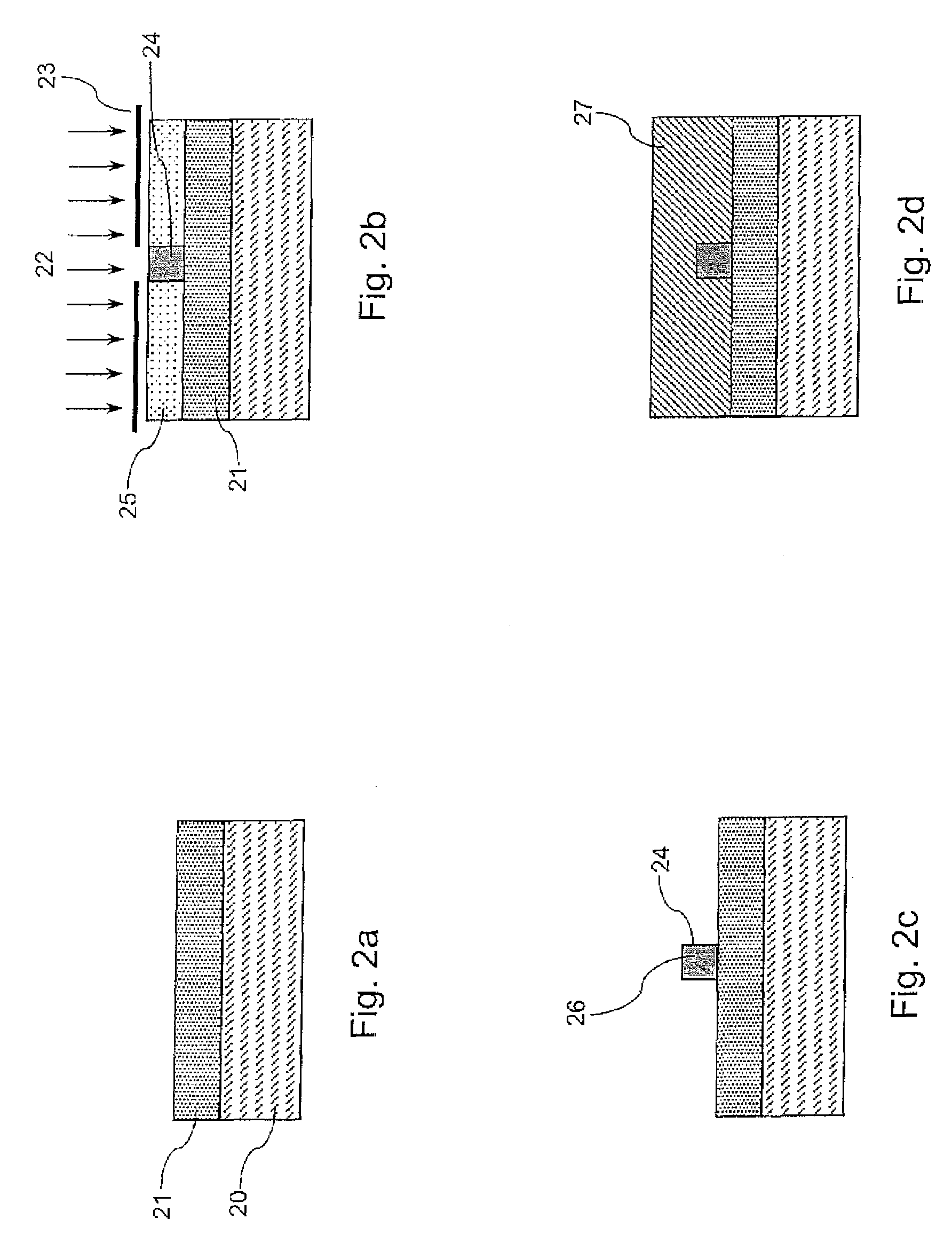
[0132]In this example, the light guiding core layer is deposited by a two-stage extrude-and-spin process, and the lower cladding and upper cladding layers are each deposited by a single stage extrusion process.
[0133]Following the procedure disclosed in U.S. Pat. No. 6,818,721, a lower refractive index polymer. A was prepared with a viscosity of 2500 cP (at 20° C.) and a refractive index (measured at 20° C. on an Abbé refractometer with room light) of 1.483. A higher refractive index polymer B was prepared with a viscosity of 2200 cP (at 20° C.) and a refractive index of 1509 (at 20° C.). A suitable photo-initiator was added to both polymer A and polymer B, without the presence of any solvent.
[0134]Once polymers A and B had been obtained, the waveguides were fabricated using a process summarised in the flowchart shown in FIG. 5. A substrate comprising a 0.175 mm thick sheet of the polycarbonate UV® (Bayer, with a co-extruded UV absorbing layer) was cut to the appropriate size (400 mm...
example 2
[0138]In this example, the lower cladding and core layers are each deposited by a two-stage extrude-and-spin process, and the upper cladding layer deposited by a single stage extrusion process.
[0139]Lower refractive index polymer A and higher refractive index polymer B, each with a suitable photo-initiator, and a polycarbonate substrate, were each prepared as described in Example 1. Polymer A was extrusion coated onto the polycarbonate substrate using the FAStar Advantage III extrusion coating system, and the substrate transferred to the SSEC 3400ML spinner where the layer was further planarised by spinning at 1500 rpm for 15 seconds. The layer was then blanket cured with UV light from the Tamarack PRX8000 flood illuminator to form a lower cladding layer.
[0140]Polymer B was then extruded using the FAStar Advantage III extrusion coating system, and the substrate transferred to the SSEC 3400ML spinner where the layer was further planarised by spinning at 1500 rpm for 15 seconds to for...
example 3
[0142]In this example, the lower cladding layer is deposited by a single stage extrusion process, and the core and upper cladding layers are each deposited by a two-stage extrude-and-spin process.
[0143]Lower refractive index polymer A and higher refractive index polymer B, each with a suitable photo-initiator, and a polycarbonate substrate, were each prepared as described in Example 1. Polymer A was extrusion coated onto the polycarbonate substrate, and blanket cured with UV light to form a lower cladding layer.
[0144]Polymer B was then extruded using the FAStar Advantage III extrusion coating system, and the substrate transferred to the SSEC 3400ML spinner where the layer was further planarised by spinning at 1500 rpm for 15 seconds to form a core layer 11 μm thick. This layer was then image-wise exposed to UV light through a mask, and developed with isopropanol to leave exposed material in the form of an array of elongated channels.
[0145]An upper cladding layer was then deposited b...
PUM
 Abstract
Description
Claims
Application Information
 - R&D
- Intellectual Property
- Life Sciences
- Materials
- Tech Scout
- Unparalleled Data Quality
- Higher Quality Content
- 60% Fewer Hallucinations
Browse by: Latest US Patents, China's latest patents, Technical Efficacy Thesaurus, Application Domain, Technology Topic, Popular Technical Reports.
© 2025 PatSnap. All rights reserved.Legal|Privacy policy|Modern Slavery Act Transparency Statement|Sitemap|About US| Contact US: help@patsnap.com


