

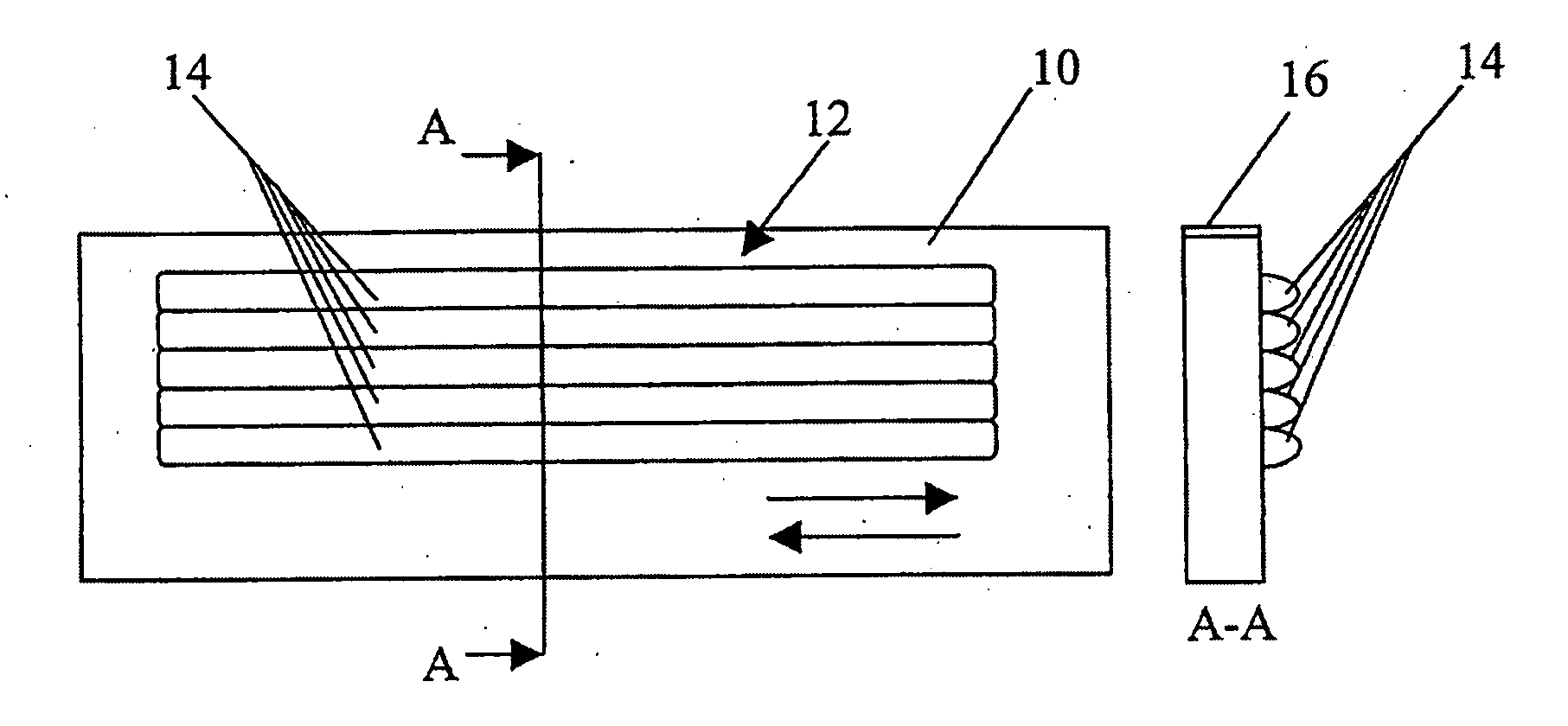
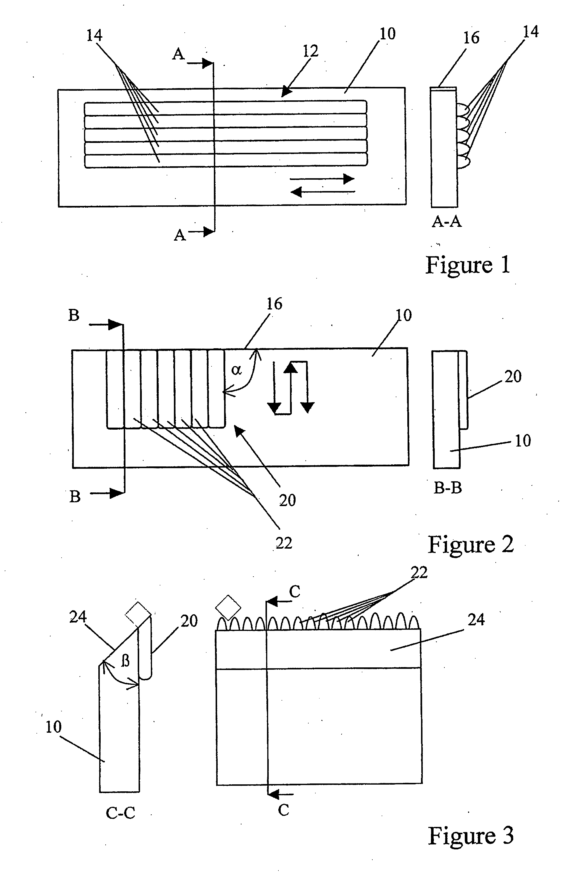
Cutting implement
a technology of cutting implements and cutting edges, applied in the field of cutting implements, can solve the problems of large heat, affecting the substrate, pta damage to the sharp or near sharp cutting edge, etc., and achieve the effect of effective and durable implements
- Summary
- Abstract
- Description
- Claims
- Application Information
AI Technical Summary
Benefits of technology
Problems solved by technology
Method used
Image

Examples
example 1
[0049]In this example, an interface layer of nickel based metallic binder matrix (NiBSi) such as Deloro PW was deposited in a traversing manner parallel to the edge of the substrate to produce a crack free layer of approximately 1 mm in thickness on the substrate. A hardfacing component comprising tungsten carbide (WC / Co) particles of monophase tungsten with a cobalt coating at the rate of 88:12, such as Ampereit 522.2, HCStarck, combined with NiBSi was deposited in a traversing manner with a thickness of approximately 1 mm at an angle of approximately α=90° to the edge of the substrate. However, it will be appreciated that the WC / Co particles of the hardfacing component may be replaced with tungsten melt carbide, WC / W2C. The size of the WC / Co particles was approximately in the range 45 to 90 μm, a typical hard phase particle size range for hard facing blends. The process parameters for this example are set out in Table 1(a) below:
Interface Layer:Laser Power2000 WNiBSiSpot size5 mmD...
example 2
[0051]In this example, the beads of the hardfacing layer were deposited in a meandering pattern using the following process parameters:
Interface Layer:Laser Power1500 WNiBSiSpot size5 mmDeposit Velocity800 mm / minPowder feed9 g / minBead pitch2.5 mm / layerSupply streamArgon#beads5
Hardfacing Component Layer:Laser Power1500 WNiBSi + WC / Co50:50Spot size5 mmDeposit Velocity300 mm / minPowder FeedNiBSi4 g / minWC / Co6 g / minBead pitch2.5 mm / layerSupply streamArgonmeander
Table 2
[0052]In this case, crack free layers were also produced.
example 3
[0053]In this example, an interface layer of NiBSi was deposited in a traversing manner parallel to the edge of the substrate to produce a crack free layer of approximately 1 mm in thickness on the substrate. A hardfacing component comprising sintered and broken titanium carbide (TiC) particles, available from HCStarck, combined with NiBSi was deposited in a traversing manner with a thickness of approximately 1 mm at an angle of approximately α=90° to the edge of the substrate. The process parameters for this example are set out in Table 2(a) below:
Interface Layer:Laser Power2000 WNiBSiSpot size5 mmDeposit Velocity800 mm / minPowder feed13 g / minBead pitch2.5 mm / layerSupply streamArgon#beads13
Hardfacing Component Layer:Laser Power2500 WNiBSi + TiC40:60Spot size5 mmDeposit Velocity400 mm / minPowder FeedNiBSi5 g / minTiC4.5 g / minBead pitch2.4 mm / layerSupply streamArgon#beads72
Table 3
[0054]The cutting edge produced was less wavy than that of example 1 and only some pores were found. In the i...
PUM
| Property | Measurement | Unit |
|---|---|---|
| Angle | aaaaa | aaaaa |
| Angle | aaaaa | aaaaa |
| Length | aaaaa | aaaaa |
Abstract
Description
Claims
Application Information