Composite Spark Plug

Inactive Publication Date: 2007-11-15
PASSAIC RIVER CO INC
View PDF64 Cites 28 Cited by
  • Summary
  • Abstract
  • Description
  • Claims
  • Application Information

AI Technical Summary

Benefits of technology

[0036]The present invention also provides a positive gas seal for the internal components of the spark plug against gasses and pressures resulting from the combustion process. The ceramic cone of the insulator exposed to the combustion chamber is provided with a center core into which the center electrode is positioned. The electrode is provided with an extension

Problems solved by technology

While these materials will reduce electrode erosion for typical low power discharge (less than 1 ampere peak discharge current) spark plugs and perform to requirements for 109 cycles, they will not withstand the high coulomb transfer of high power discharge (greater than 1 ampere peak discharge current).
While this will increase the discharge power of the spark, the designs are inefficient, complex and none deal with the accelerated erosion associated with high power discharge.
The use of two spark gaps in a singular spark plug to ignite fuel in any internal combustion spark ignited engine that utilizes electronic processing to control fuel delivery and spark timing could prove fatal to the operation of the engine as the EMI/RFI emitted by the two spark gaps could cause the central processing unit to malfunction.
Capacitance is not disclosed and nowhere is there any mention of the electromagnetic and radio frequency interference created by the non-resistor spark plug, which if not properly shielded against EMI/RFI emissions, could cause the central processing uni

Method used


Image

  • Composite Spark Plug
  • Composite Spark Plug
  • Composite Spark Plug

Examples


Embodiment Construction

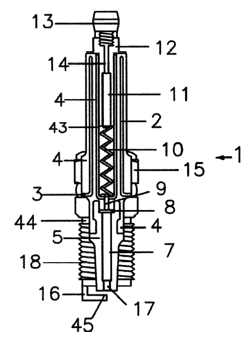
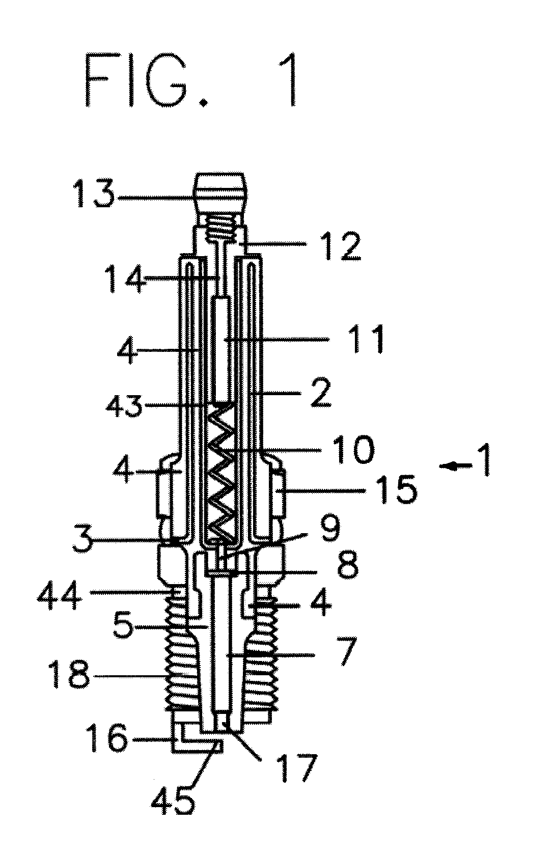
[0045]Referring now to the drawings, in particular FIG. 1, a spark plug or ignition device for spark ignited, internal combustion engines in accordance with the present invention is shown generally as 1. The spark plug or ignition device 1 consists of a preferably metal casing or shell 15 having a substantially cylindrical base 44, which may have external threads 18, formed thereon for engagement with the cylinder head (not shown) of the spark ignited internal combustion engine (not shown). The cylindrical base 44 of the spark plug shell has a generally flattened surface perpendicular to the longitudinal axis of the spark plug 1 to which a ground electrode 16 is affixed, preferably by conventional welding. In an embodiment of the invention, the ground electrode 16 has a preferably rounded tip 45 of Rhenium / Tungsten sintered compound, which resists the erosion of the electrode 16 due to high power discharge, as further disclosed herein.

[0046]The spark plug or ignition device 1 includ...


PUM


Abstract

A composite ignition device includes a positive electrode having a tip formed thereon that is bonded to a first insulator to form a firing cone assembly. A second insulator having a negative capacitive element embedded therein is attached to the firing cone assembly. A positive capacitive element is disposed in the second insulator and is separated from the negative capacitive element by the second insulator. The positive capacitive element is coupled to the positive electrode. The positive and negative capacitive elements form a capacitor. A resistor is coupled to the positive capacitive element. An electrical connector is coupled to the resistor and attached to the second insulator. A shell includign a negative electrode having a tip is attached to the second insulator and the firing core assembly and coupled to the negative capacitive element. The negative electrode tip is spaced apart from the positive electrode tip.

Description

CROSS-REFERENCE TO RELATED APPLICATIONS[0001]This application claims priority to and the benefit of the filing of U.S. Provisional Patent Application Ser. No. 60 / 799,926, entitled “Composite Spark Plug”, filed on May 12, 2006, and the specification thereof is incorporated herein by reference.BACKGROUND OF THE INVENTION[0002]The present invention relates to spark plugs used to ignite fuel in internal combustion spark—ignited engines. Present day spark plug technology dates back to the early 1950's with no dramatic changes in design except for materials and configuration of the spark gap electrodes. These relatively new electrode materials such as platinum and iridium have been incorporated into the design to mitigate the erosion common to all spark plugs electrodes in an attempt to extend the useful life. While these materials will reduce electrode erosion for typical low power discharge (less than 1 ampere peak discharge current) spark plugs and perform to requirements for 109 cycle...

Claims


Application Information

Patent Timeline
IPC IPC(8): H01K1/62H01J17/34H01J29/96H01J7/44
CPCH01T21/02H01T13/40H01T13/34H01T13/41F02P13/00H01T13/00
Inventor CAMILLI, LOUIS S.
Owner PASSAIC RIVER CO INC
Why Eureka
Try Eureka