Wavelength Control of an External-Cavity Tuneable Laser

a tuneable laser and wavelength control technology, applied in semiconductor lasers, instruments, optics, etc., can solve the problems of spatial loss, reduced output power of transmitters, and inability to accurately control the positioning of tunable elements associated with transmitter lasers over the entire tuning and operating temperature range, so as to increase the amplitude modulation of laser output signals, increase the phase shift, and reduce spatial loss

Inactive Publication Date: 2007-11-22
GOOGLE LLC
View PDF10 Cites 17 Cited by
  • Summary
  • Abstract
  • Description
  • Claims
  • Application Information

AI Technical Summary

Benefits of technology

[0020] Depending on the amplitude of the voltage applied to the tunable mirror, VTM, the tuneable mirror reflects radiation only at a given wavelength λTMThe spectral response of the tuneable mirror is generally a curve, with a shape similar for example to that of a Lorentzian curve, centred at λTM and characterized, inter alia, by the bandwidth at FWHM. The tuneable mirror is driven with an alternating voltage of amplitude VTM and frequency fA to prevent deterioration of the liquid crystal due to dc stress.
[0023] Frequency modulation of the applied voltage induces variations of the refractive index of the LC material which in turn induces a phase shift of the optical beam that has interacted with the LC material. To a first approximation, phase shifts are proportional to the thickness of LC material that is traversed by the optical beam. In single-mode tuneable lasers, relatively high phase shifts induce relatively large frequency modulations of the laser output signal. This effect is particularly detrimental if a spectrally selective loss element, such as a grid etalon, is present in the laser cavity, because it increases the amplitude modulation of the laser output signal.
[0034] Analysis of the modulated component of the laser output power can be performed together (or sequentially) with the analysis of the output power (the total output signal that comprises also the modulated component) in order to centre the cavity mode with a spectrally selective loss element, such as a grid etalon. In a preferred embodiment the loss element is grid etalon that defines a plurality of pass bands substantially aligned to corresponding channels of a wavelength grid. Centering of the cavity mode to a pass band of the spectrally selective loss element, i.e., mode stabilization of the laser output signal, can be attained by maximizing the laser output power. Measurements of the modulated component and of the “total” output power can be advantageously carried out by means of the same photodiode placed at the laser output.

Problems solved by technology

As DWDM uses narrower channel spacing, accuracy and control in the positioning of the tunable elements associated with the transmitter lasers over the entire tuning and operating temperature range has become an important issue.
Non optimal positioning of tunable elements results in spatial losses and reduced output power of the transmitter.
Inventors have noted that discrete wavelength selection of an intracavity element which is continuously tuneable can limit the accuracy of wavelength tuning and makes the use of a wavelength locking system necessary to maintain the wavelength to the desired operating value.
They have further remarked that the use of a wavelength locking system, also if integrated, increases the cost of the laser module and may be prejudicial to the compactness of the laser system.
Inventors have noted that adjusting the cavity length to bring the wavelength to a local maximum of the transmission spectrum of the grid etalon involves mechanical movements of at least an element of the laser cavity, e.g., the end mirror, which may affect the reliability of the laser system.
Inventors have noticed that, for applications to single-mode tuneable lasers, relatively high phase changes cause a relatively large wavelength oscillation and intensity variation, which may cause instability of the laser output signal and / or broadening of the spectral linewidth.

Method used


Image

  • Wavelength Control of an External-Cavity Tuneable Laser
  • Wavelength Control of an External-Cavity Tuneable Laser
  • Wavelength Control of an External-Cavity Tuneable Laser

Examples


Embodiment Construction

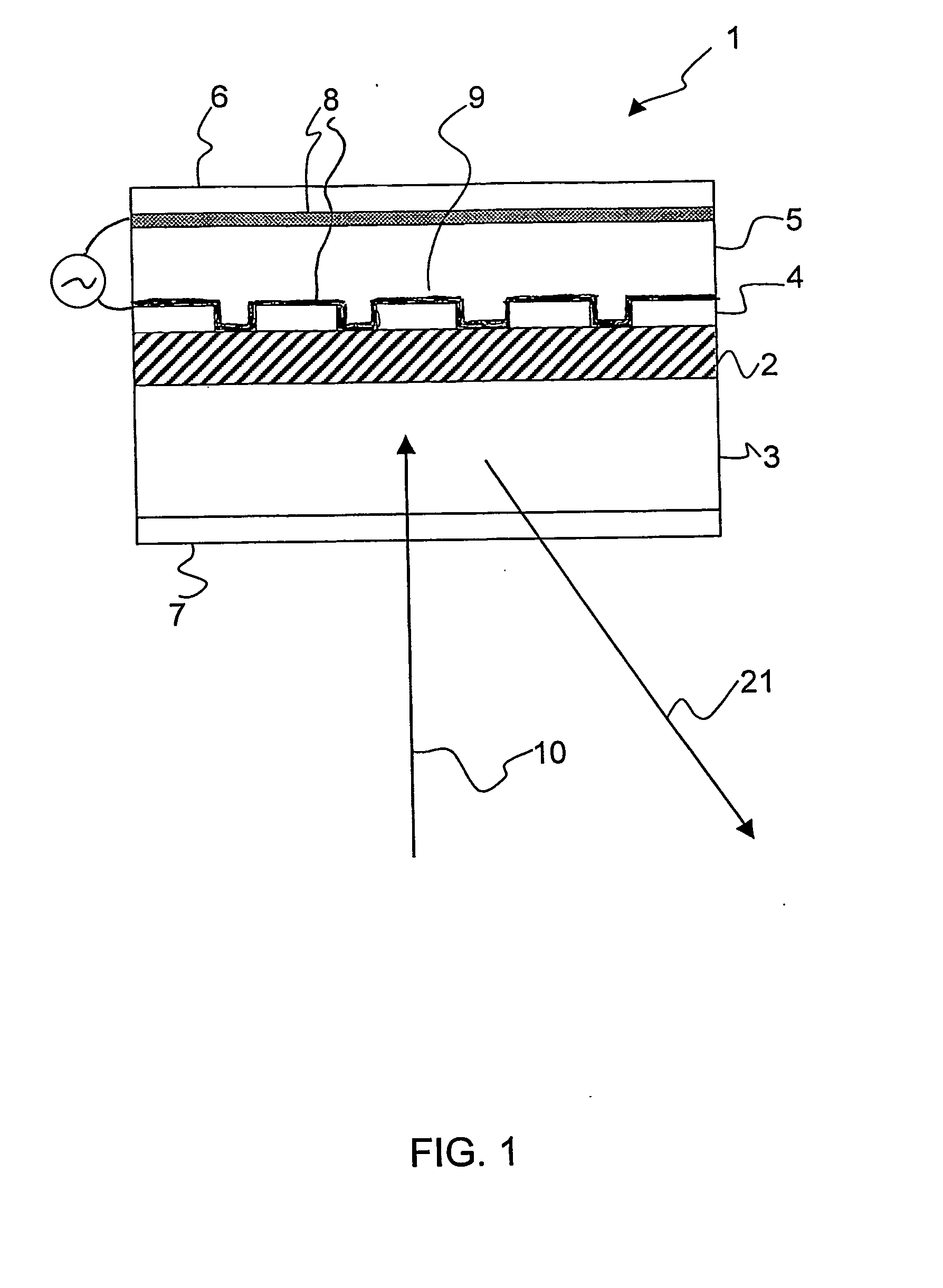
[0056] The tuneable mirror is an electro-optic element, in which tunability is accomplished by using a material with voltage dependent refractive index, preferably a liquid crystal (LC) material. A preferred embodiment of the tunable mirror is shown in FIG. 1. Tunable mirror 1 comprises a waveguide 2 formed onto a substrate 3 and a diffraction grating 4 formed on waveguide 2. Over the diffraction grating 4 a cladding layer 5 that fills at least the interstices of the diffraction grating is formed, said cladding layer being made of a LC material. The thickness of the LC material is preferably not larger than 2 μm, more preferably of about 1 μm. Optionally, there may be an anti-reflection coating 6 over the cladding layer and / or an anti-reflection coating 7 on the surface of substrate 3, which is opposite to the waveguide. Two transparent conductors 8 and 9 are placed on opposite surfaces of the liquid crystal layer. A more detailed description of the structure of a tuneable mirror ac...


PUM


Abstract

A method of controlling an external-cavity tuneable laser which has a wavelength-elective tuneable mirror, in which wavelength selectivity is achieved by an electrical signal provided by an alternating voltage. The tuneable mirror has a liquid crystal material, a diffraction grating and a planar waveguide optically interacting with the grating. The diffraction grating and the waveguide form a resonant structure that reflects only a selected resonance wavelength from among all the other wavelengths impinging thereon. Depending on the amplitude of the voltage applied to the tunable mirror, the tuneable mirror reflects radiation only at a given wavelength. The lasing output wavelength of the laser is selected to correspond to the resonance wavelength of the tuneable mirror. Accurate selection of the emission wavelength (frequency) of the tuneable laser by the tuneable mirror can be derived from the analysis of the signal modulation induced by the AC voltage applied to the tuneable mirror.

Description

[0001] The invention concerns an external-cavity tuneable laser especially adapted for wavelength-division multiplexed optical communication networks. In particular, the invention relates to a method of selecting and controlling the position of a tuneable element in an external-cavity tuneable laser. RELATED ART [0002] The use of lasers as tuneable light source can greatly improve the reconfigurability of wavelength-division multiplexed (WDM) systems or of the newly evolved dense WDM (DWDM). For example, different channels can be assigned to a node by simply tuning the wavelength. Also, tuneable lasers can be used to form virtual private networks based on wavelength routing, i.e., photonic networks. [0003] Different approaches can be used to provide tunable lasers, distributed Bragg reflector lasers, VCSEL lasers with a mobile top mirror, or external-cavity diode lasers. External-cavity tunable lasers offer several advantages, such as high output power, wide tuning range, good side ...

Claims


Application Information

Patent Timeline
Patent Type & Authority Applications(United States)
IPC IPC(8): H01S5/14H01S5/022H01S5/06H01S5/062
CPCG02F2203/055H01S3/105H01S3/1065H01S3/1398H01S5/02216H01S5/141H01S5/0617H01S5/0622H01S5/0683H01S5/101H01S5/02284H01S5/02251H01S5/14
Inventor CATTELLAN, SUSANNA MARIAROMANO, ANDREADE DONNO, MARCOPIANCIOLA, AURELIO
Owner GOOGLE LLC
Why Eureka
Try Eureka