Reactor of selective-permeation membrane type

a membrane reactor and selective technology, applied in the direction of membranes, separation processes, physical/chemical process catalysts, etc., can solve the problems of large decrease in separation/recovery efficiency, physical and chemical damage of selective membrane, and inability to achieve sufficient mixed gas separation effect, etc., to achieve high porosity, large pore size, and high permeation rate

Active Publication Date: 2007-11-22
NGK INSULATORS LTD
View PDF6 Cites 15 Cited by
  • Summary
  • Abstract
  • Description
  • Claims
  • Application Information

AI Technical Summary

Benefits of technology

[0014] In contrast, the patent document 2 proposes a method of inserting straightening vanes into the reactor in order to improve the contact efficiency between the mixed gas and the selectively permeable membrane.
[0048] In a preferred embodiment of the selectively permeable membrane reactor according to the present invention, the foamed body is divided into a plurality of sections, and stirring means (e.g. straightening vanes provided perpendicularly to the flow of the raw material gas) for stirring the raw material gas supplied to the internal space of the reaction tube through the supply port to disturb the flow of the raw material gas are provided between the foamed sections. Therefore, the contact efficiency between the mixed gas and the selectively permeable membrane can be improved.

Problems solved by technology

However, according to the above selectively permeable membrane reactor, since the catalyst is provided as a packed bed between the separation tube having the selectively permeable membrane on its surface and the reaction tube, there arises a problem that the catalyst contacts the selectively permeable membrane to cause the selectively permeable membrane to physically and chemically deteriorate.
In particular, a decrease in separation / recovery efficiency may occur to a large extent as the flow rate of the raw material gas increases.
As a result, there arises a problem that a sufficient mixed gas separation effect is not achieved.

Method used


Image

  • Reactor of selective-permeation membrane type
  • Reactor of selective-permeation membrane type
  • Reactor of selective-permeation membrane type

Examples


example 1

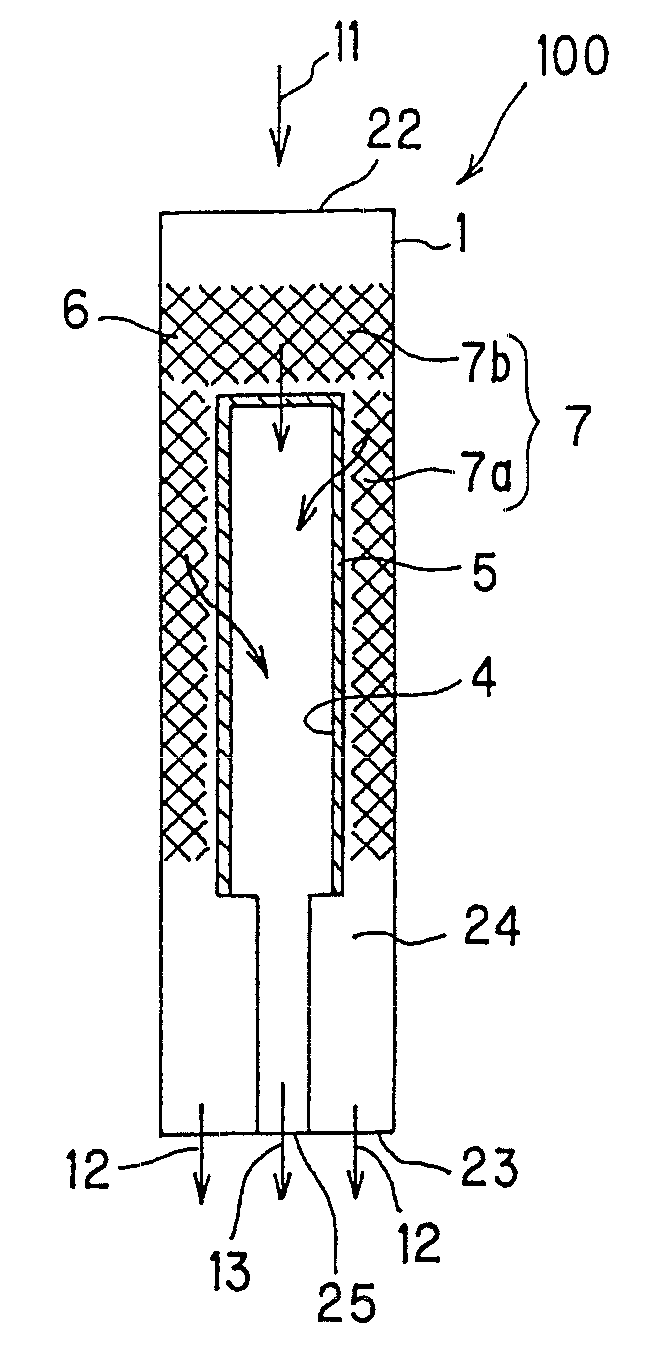
[0084] A selectively permeable membrane reactor was produced which has the same shape as the selectively permeable membrane reactor 100 shown in FIG. 1. An alumina porous body (outer diameter: 10 mm, length: 75 mm) in the shape of a bottomed cylinder of which one end was closed was used as the separation tube. A palladium (Pd)-silver (Ag) alloy film selectively allowing hydrogen to pass through was formed by plating on the surface of the alumina porous body as the selectively permeable membrane. The composition of the film was adjusted so that Pd was 75 mass % and Ag was 25 mass % taking hydrogen permeability into consideration. The thickness of the film was 2.5 μm. As the catalyst, a slurry including a powdered ruthenium catalyst was carried by dipping over the entire surface of a disk-shaped foamed body (corresponding to the foamed body 7b in FIG. 1) and a cylindrical foamed body (corresponding to the foamed body 7a in FIG. 1). The disk-shaped foamed body was formed of cordierite ...

example 2

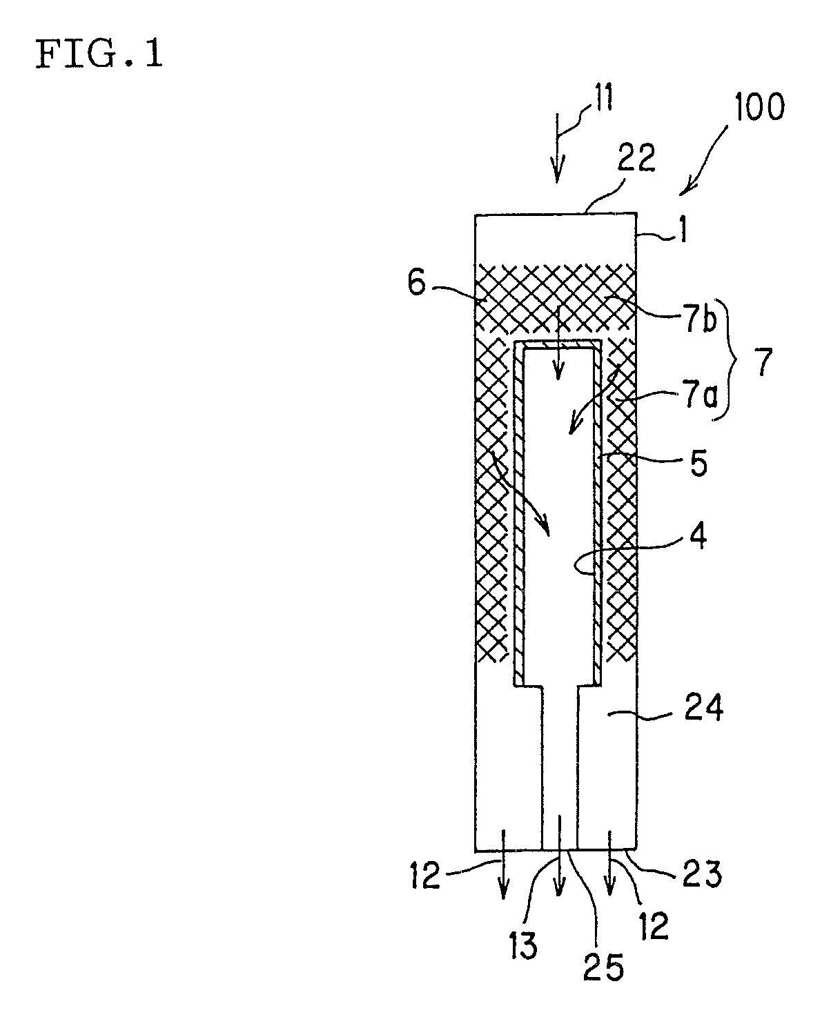
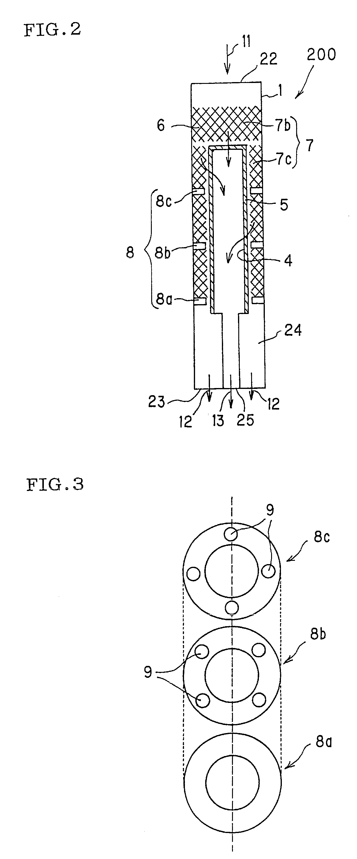
[0085] A selectively permeable membrane reactor was produced which was similar to the selectively permeable membrane reactor 200 shown in FIG. 2. An alumina porous body (outer diameter: 10 mm, length: 75 mm) in the shape of a bottomed cylinder of which one end was closed was used as the separation tube. A palladium (Pd)-silver (Ag) alloy film selectively allowing hydrogen to pass through was formed by plating on the surface of the alumina porous body as the selectively permeable membrane. The composition of the film was adjusted so that Pd was 75 mass % and Ag was 25 mass % taking hydrogen permeability into consideration. The thickness of the film was 2.5 μm. As the catalyst, a slurry including a powdered ruthenium catalyst was carried by dipping over the entire surface of a disk-shaped foamed body (corresponding to the foamed body 7b in FIG. 2) and a cylindrical foamed body divided into three sections (corresponding to the foamed body 7c in FIG. 2). The disk-shaped foamed body was ...

example 3

[0086] A selectively permeable membrane reactor similar to the selectively permeable membrane reactor 200 shown in FIG. 2 was produced in the same manner as in Example 2 except that the disk-shaped and cylindrical foamed bodies had a porosity of 90%.


PUM

PropertyMeasurementUnit
pore sizeaaaaaaaaaa
porosityaaaaaaaaaa
distanceaaaaaaaaaa

Abstract

A selectively permeable membrane reactor 100 includes a reaction tube 1 including an internal space 24 having a supply port 22 as an inlet port for a raw material gas 11 and a discharge port 23 as an outlet port for an unseparated gas 12, and a separation tube 4 inserted into the internal space 24 of the reaction tube 1. The separation tube 4 includes a selectively permeable membrane 5 exhibiting selective permeability for a specific component on a surface facing the internal space 24 of the reaction tube 1, and a process port 25 as an outlet port for a separated gas 13 which has passed through the selectively permeable membrane 5, and a catalyst for promoting a chemical reaction is provided in the internal space 24 of the reaction tube 1 excluding the separation tube 4. The selectively permeable membrane reactor 100 is characterized in that a catalyst is carried by a foamed body 7 having porous structure to form a foam-molded product and suppresses physical and chemical deterioration in the selectively permeable membrane and allows a mixed gas produced by a catalytic reaction to be efficiently separated and taken out through the selectively permeable membrane.

Description

TECHNICAL FIELD [0001] The present invention relates to a selectively permeable membrane reactor used to produce, separate, and take out a specific gas component from a raw material gas utilizing chemical reaction. BACKGROUND ART [0002] Hydrogen (gas) has been widely used as a basic material gas in the field of petrochemistry. In recent years, hydrogen has attracted attention as a clean energy source. Hydrogen may be obtained by producing a hydrogen-containing mixed gas from a main raw material gas such as a hydrocarbon (e.g. methane, butane, or kerosene) or an oxygen-containing hydrocarbon (e.g. methanol, ethanol, or dimethyl ether) and a secondary raw material gas such as water (steam), carbon dioxide, or oxygen by utilizing a chemical reaction such as a reforming reaction, a partial oxidation reaction, or a decomposition reaction, and separating and taking out hydrogen from the mixed gas using a selectively permeable membrane (e.g. palladium alloy membrane) which selectively allo...

Claims


Application Information

Patent Timeline
Patent Type & Authority Applications(United States)
IPC IPC(8): B01J7/02
CPCB01D53/228C01B2203/1241B01D2325/10B01J8/009B01J8/025B01J8/0257B01J8/0278B01J8/0292B01J19/006B01J19/2475B01J23/44B01J23/50B01J35/04B01J35/065B01J2208/0084B01J2219/00777C01B3/326C01B3/38C01B3/386C01B3/503C01B3/505C01B2203/0233C01B2203/0261C01B2203/0277C01B2203/041C01B2203/047C01B2203/0475C01B2203/048C01B2203/1029C01B2203/1041C01B2203/1064B01D53/229Y02P20/52
Inventor MORI, NOBUHIKONAKAMURA, TOSHIYUKITAKAHASHI, AKIRA
Owner NGK INSULATORS LTD
Why Eureka
Try Eureka