

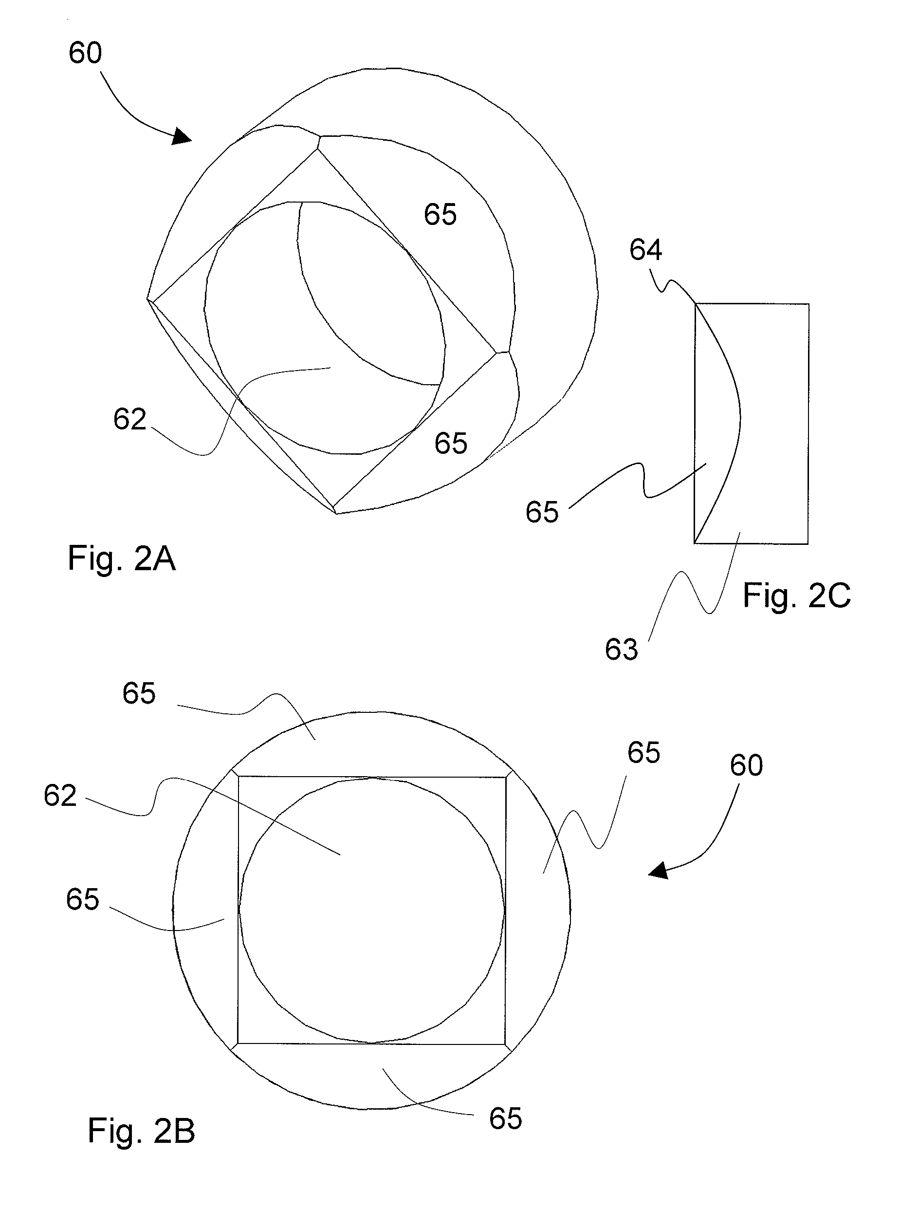
Multi-faceted optical reflector
a multi-faceted, optical reflector technology, applied in the direction of catheters, instruments, diagnostics using spectroscopy, etc., can solve the problems of harmful side effects, high cost, and inflexible techniques, and achieve the effect of reducing the reliance on inflexible, complex and/or difficult to assemble components that inhibit prior art devices, reliable, simplified and cost-effective optical components
- Summary
- Abstract
- Description
- Claims
- Application Information
AI Technical Summary
Benefits of technology
Problems solved by technology
Method used
Image

Examples
Embodiment Construction
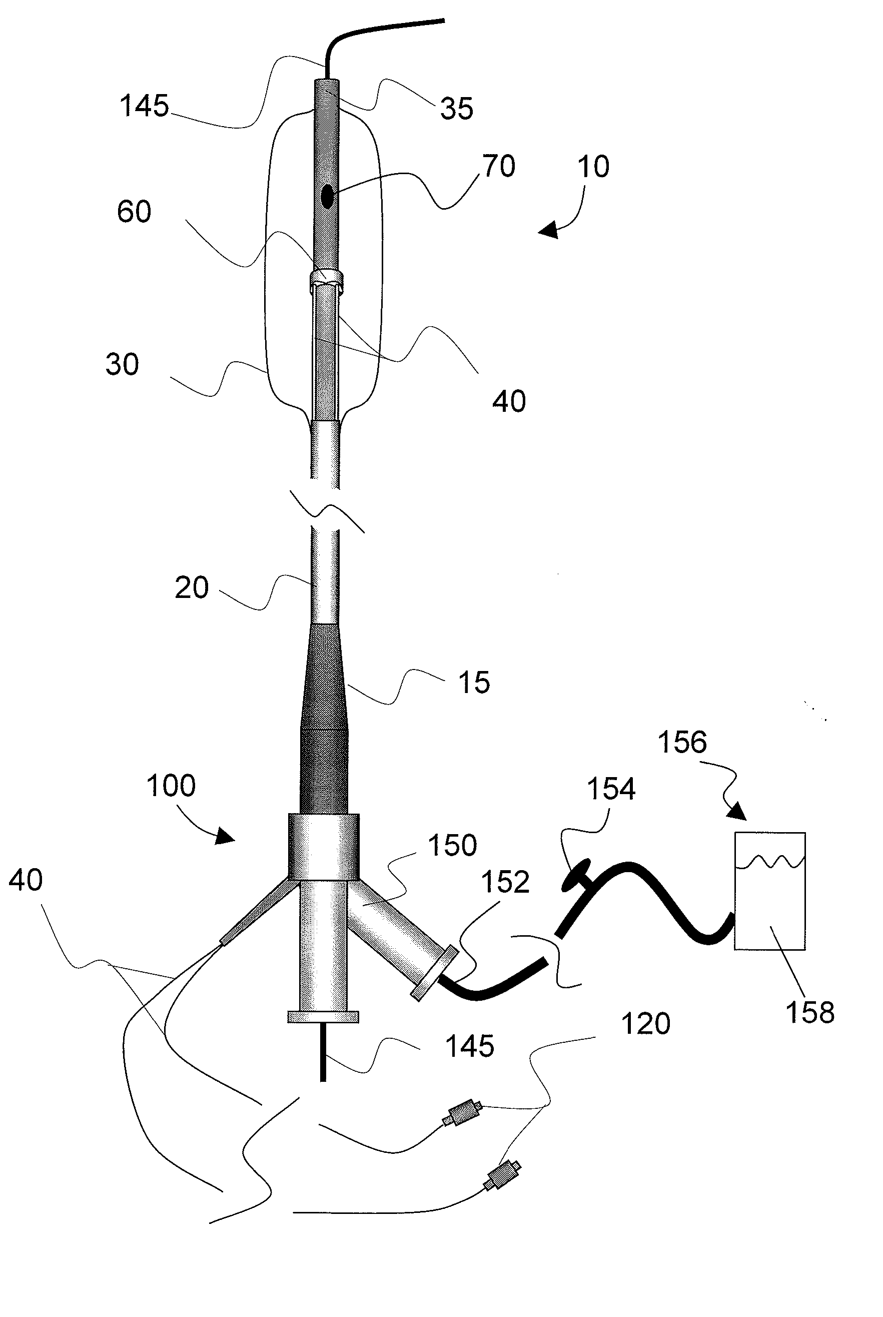
[0091] The accompanying drawings are described below, in which example embodiments in accordance with the present invention are shown. Specific structural and functional details disclosed herein are merely representative. This invention may be embodied in many alternate forms and should not be construed as limited to example embodiments set forth herein.
[0092] Accordingly, specific embodiments are shown by way of example in the drawings. It should be understood, however, that there is no intent to limit the invention to the particular forms disclosed, but on the contrary, the invention is to cover all modifications, equivalents, and alternatives falling within the spirit and scope of the claims. Like numbers refer to like elements throughout the description of the figures.
[0093] It will be understood that, although the terms first, second, etc. may be used herein to describe various elements, these elements should not be limited by these terms. These terms are used to distinguish ...
PUM
| Property | Measurement | Unit |
|---|---|---|
| Diameter | aaaaa | aaaaa |
| Length | aaaaa | aaaaa |
| Length | aaaaa | aaaaa |
Abstract
Description
Claims
Application Information