Method of simultaneous singulation and edge sealing of plastic displays

a plastic display and singulation technology, applied in paper/cardboard containers, transportation and packaging, manufacturing tools, etc., can solve the problems of inflexibility and durability, difficult roll-to-roll manufacturing of gasket seals, and inability to meet the needs of continuous production, so as to avoid the tendency of individual layers, and achieve the effect of unique electro-optical features

Active Publication Date: 2007-12-06
KENT DISPLAY SYST
View PDF23 Cites 27 Cited by
  • Summary
  • Abstract
  • Description
  • Claims
  • Application Information

AI Technical Summary

Benefits of technology

[0022]Cholesteric liquid crystal material possesses unique electro-optical features and offers numerous advantages over other display materials. If cholesteric liquid crystal is used to make the plastic LCD, multiple layers can be stacked to produce more than one reflected color.
[0023]Edge sealing [1] is used in a multilayer stacked display to avoid the tendency of individual layers to easily delaminate. The laser-welded edge seal according to the present invention is believed to have practical value in manufacturing, since all layers can be easily made in a roll-to-roll process and the singulation and bonding of all substrates in the display can take place in one step.
[0024]An advantage to the laser edge seal according to the invention is that the display may be cut to any polygon or shape that is determined by a simple graphic image drawn using Auto CAD or Corel Draw [15] software. In this way, the singulation and simultaneous edge seal lead to rapid prototyping with little to no retooling. In general, as long as the actively switching conductor is not cut with the laser, no shorting from the top substrate to the bottom substrate will occur. Even if a conductor is shorted at the edge after being laser cut, it is possible to repair the display using a laser to burn out the short (e.g., a Nd:YAG laser in the case of ITO electrodes) or to burn out the short by driving the display with a sufficient current that would be apparent to those of ordinary skill in the art in view of this disclosure. Given the proper cutting conditions and materials, it is also possible to laser cut through the conductor without creating shorts.

Problems solved by technology

For glass LCDs, two big challenges remain; namely, flexibility and durability.
Oftentimes the polymer walls created during the encapsulation process are not very strong since they can have a width on the scale of micron to sub-micron.
However, it is best suited to a batch process, as roll-to-roll manufacturing a gasket seal is technologically challenging in that both the LC and the resin seal must be applied (as liquids) simultaneously.
External adhesive tape forms a weaker bond, is less mechanically robust and is generally quite permeable and susceptible to water-damage.
However, it is not very mechanically robust, as it tears easily.
A limitation of conventional laser welding is the understanding that only pure thermoplastic materials in contact with one another can be laser welded because impurities in the area to be bonded can contaminate the bond and cause its failure.

Method used


Image

  • Method of simultaneous singulation and edge sealing of plastic displays
  • Method of simultaneous singulation and edge sealing of plastic displays
  • Method of simultaneous singulation and edge sealing of plastic displays

Examples


example 1

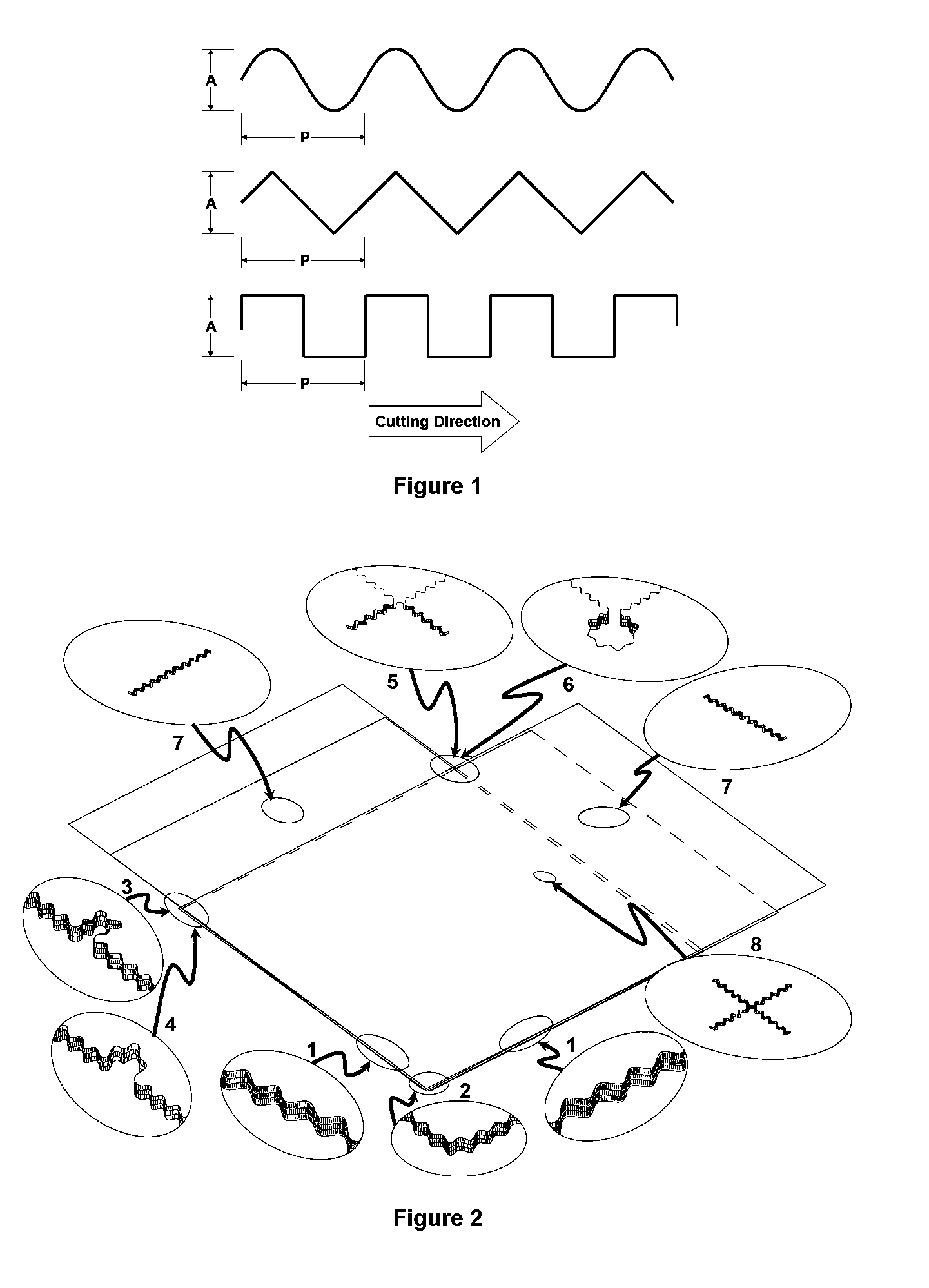
Single Layer Pixelated Display with ITO Conductor

[0054]An encapsulated liquid crystal layer using droplet dispersions by PIPS method was fabricated between two ITO-patterned 2 mil thick PET sheets (pixilated by rows and columns; FIG. 2). Solutions of an acrylate-based pre-polymer were vortex-mixed and then added to the cholesteric liquid crystal. Once this was vortex-mixed, 4.5 μm plastic spherical spacers were added to the mixture to preserve substrate spacing before polymerization. The system was mixed again via ultrasonic agitation (to suspend the spacers) and then pipetted between two PET substrates with conductive electrodes. The bead of liquid was then rolled down between the PET sheets using a hand roller and any excess was cleaned off. The material was polymerized under an Electro-lite ELC 4001 UV source as known in the art. During the curing process, the pre-polymer mixture polymerized, causing the liquid crystal to phase separate into droplets. After curing, an LCD was cut...

example 2

Multilayer Pixelated Display with ITO Conductor

[0056]Three encapsulated liquid crystal layers using droplet dispersions by PIPS method were fabricated between four ITO-patterned 2 mil thick PET sheets (pixelated by rows and columns; FIG. 2). Solutions of an acrylate-based pre-polymer were vortex-mixed and then added to the liquid crystal. Once the mixtures were vortex-mixed, 4 μm plastic spherical spacers were added to each mixture. The system was mixed again via ultrasonic agitation and then pipetted between two PET substrates with conductive electrodes. The bead of liquid was then rolled down between the PET sheets using a hand roller and any excess was cleaned off. Then each layer was individually laminated and polymerized under an Electro-lite ELC 4001 UV source. During the curing process, the pre-polymer mixture polymerized, causing the liquid crystal to phase separate into droplets. After curing, a three color LCD display was cut from the sheet using a CO2 M-300 laser marking ...

example 3

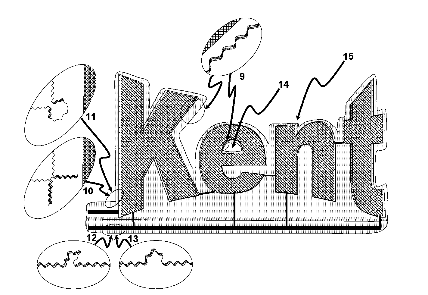
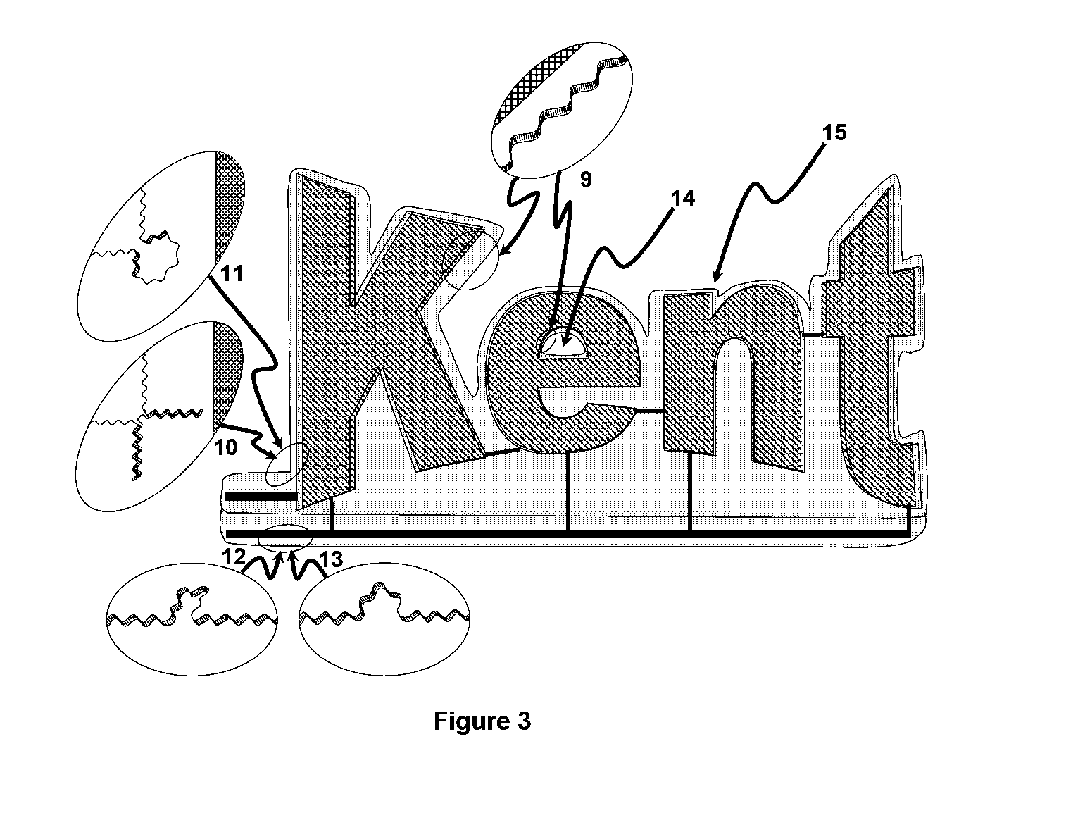
Single Layer Segmented Display with ITO Conductor

[0058]An encapsulated LC layer using droplet dispersions by PIPS method was fabricated between two segmented (see FIG. 3) ITO-patterned 2 mil thick PET sheets. Solutions of an acrylate-based pre-polymer were vortex-mixed and then added to the liquid crystal. Once this was vortex-mixed, 4.5 μm plastic spherical spacers were added to the mixture. The system was mixed again via ultrasonic agitation (to suspend the spacers) and then pipetted between two PET substrates with conductive electrodes. The bead of liquid was then rolled down between the PET sheets using a hand roller and any excess was cleaned off. The material was polymerized under an Electro-lite ELC 4001 UV. During the curing process, the pre-polymer mixture polymerized, causing the liquid crystal to phase separate into droplets. After curing, an LCD was cut from the sheet using a CO2 M-300 laser marking system built by Universal Laser Systems, Inc. (Scottsdale, Ariz.) by tra...


PUM

PropertyMeasurementUnit
thickaaaaaaaaaa
peak wavelengthsaaaaaaaaaa

Abstract

The production of liquid crystal displays (LCDS) on plastic substrates is desirable over glass substrates so that the finished product is thinner, lighter, and more robust. Plastic substrates can enable the use of new and different processing techniques which are not possible on glass such as roll-to-roll processing. This invention discusses an advancement which is laser cutting a plastic substrate and display layer. One aspect of the invention is laser cutting and welding together two or more plastic substrates and LCD layer therebetween from a larger sheet or roll of plastic LCDs.

Description

CROSS-REFERENCE TO RELATED APPLICATION[0001]This application claims the benefit of U.S. Provisional Patent Application No. 60 / 803,768 filed Jun. 2, 2006, which is incorporated herein by reference in its entirety.BACKGROUND OF THE INVENTION[0002]Most liquid crystal displays (LCDs) are made from a sandwich of liquid crystal (LC) between two glass substrates coated with a transparent conductor. The glass substrates are generally held together to a predetermined gap using an epoxy-based gasket at the edge. For glass LCDs, two big challenges remain; namely, flexibility and durability. These problems can be addressed by using plastic substrates. However, the need remains for an effective edge seal to prevent the two plastic substrates from delaminating.[0003]One advantage in using plastic to make LCDs is to make the display in a roll-to-roll process. For roll-to-roll processing to be effective, the liquid crystal material should be filled between two spaced substrates and prevented from f...

Claims


Application Information

Patent Timeline
Patent Type & Authority Applications(United States)
IPC IPC(8): B26D5/00B23Q15/00
CPCB23K26/4065B23K26/409Y10T156/1054Y10T156/10Y10T156/1057Y10T156/1052B23K26/40B23K2103/172B23K2103/42B23K2103/50Y10T83/145Y10T83/465Y10T83/647B23K26/402
Inventor SCHNEIDER, TODFRANKLIN, SEANVENKATARAMAN, NITHYADAVIS, DONALD
Owner KENT DISPLAY SYST
Why Eureka
Try Eureka