Electromagnetic-wave oscillator

a technology of electromagnetic wave and oscillator, which is applied in the direction of oscillator, basic electric elements, pulse technique, etc., can solve the problems of large space occupation of dc supply portion, large apparatus size, and restricted general or industrial use, so as to achieve efficient transmission and increase the flexibility of the design of the emw oscillator on the substrate.

Inactive Publication Date: 2007-12-06
CANON KK
View PDF12 Cites 31 Cited by
  • Summary
  • Abstract
  • Description
  • Claims
  • Application Information

AI Technical Summary

Benefits of technology

[0015]According to another aspect of the present invention, the EMW oscillating unit and the supplying unit are disposed on mutually opposite surfaces of the substrate, respectively, and the penetrating electrode is formed in the substrate to connect the EMW oscillating unit and the supplying unit. Accordingly, the flexibility of design of the EMW oscillating unit on the substrate is increased, and the possibility of interference between an electromagnetic wave radiated from the EMW radiating portion and the supplying unit is reduced.
[0016]Further, it becomes easy to dispose a curved lens plate, such as a semi-spherical lens plate, on the surface of the substrate. In this structure, it is possible to couple an electromagnetic wave radiated from the oscillator to the lens plate, and appropriately shape a beam of the electromagnetic wave. Thus, the electromagnetic wave can be efficiently transmitted from the oscillator.

Problems solved by technology

However, in those techniques, the size of an apparatus increases, and hence its general or industrial use is restricted.
It is therefore likely that the DC supplying portion occupies a considerable space, and the flexibility of design of the EMW radiating portion on the substrate is reduced.
Further, the DC supplying portion and the EMW radiating portion are disposed on the same substrate, so a THz wave emitted from the radiating portion is likely to interfere with the DC supplying portion.
Also in this respect, the flexibility of design tends to be restricted.
As a result, it is not easy to densely array THz-wave oscillators of the planar integrated type.

Method used


Image

  • Electromagnetic-wave oscillator
  • Electromagnetic-wave oscillator
  • Electromagnetic-wave oscillator

Examples


first embodiment

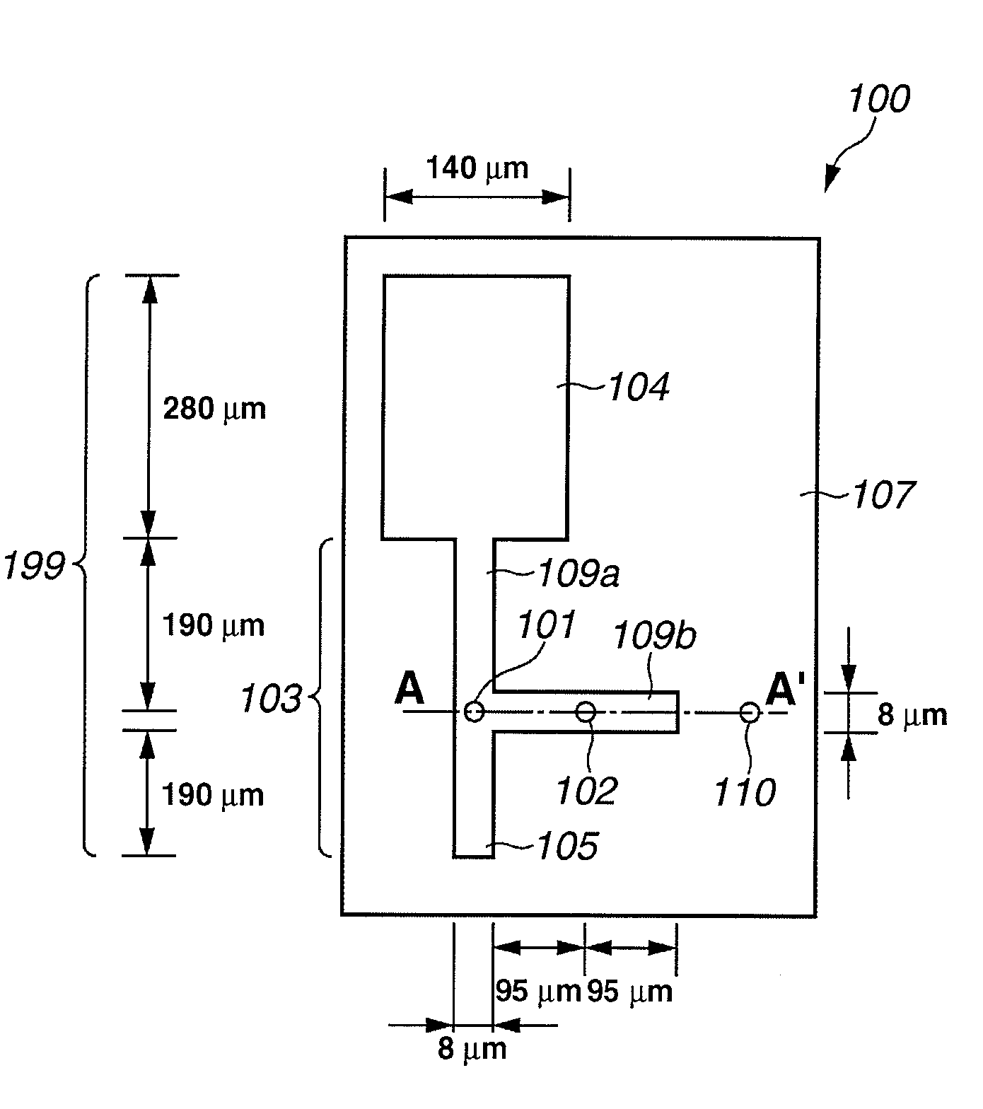
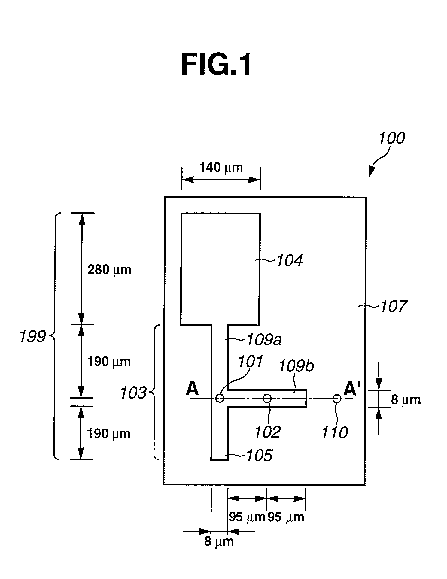
[0033]Features and operation of the oscillator 100 of the first embodiment will be described. When the DC signal is supplied to the RTD 101, induced emission of an electromagnetic wave occurs in the RTD 101. The wavelength of the electromagnetic wave is an approximately single oscillation wavelength λ (λ: the wavelength in vacuum) is a range of the THz wave, that is acquired due to the negative resistance of the RTD 101. The emitted electromagnetic wave is an electromagnetic wave with an effective wavelength λg (λg: the wavelength in the dielectric portion 107) in the dielectric portion 107, and propagates in an MSL patch antenna 199. The MSL patch antenna 199 includes the MSL resonator 103, the antenna 104, the GND portion 111, the dielectric portion 107, the RTD 101, and the like. The propagating electromagnetic wave resonates as a standing wave, and is amplified in the MSL patch antenna 199.

[0034]Under some conditions, an electromagnetic wave with the oscillation wavelength is os...

second embodiment

[0072]As described above, in the second embodiment, electromagnetic waves at low frequencies less than the cutoff frequency can be intercepted by the waveguide with a cavity in the penetrating electrode, and the low frequency noise from the DC power source can be reduced, leading to improvement of the oscillation characteristic. It is also possible to enhance the shielding effect by loading the above cavity of the waveguide with resin, or the like.

[0073]Next, details of an oscillator of a third embodiment will be described referring to FIGS. 5, 6A and 6B. FIG. 5 is a cross-sectional view illustrating the third embodiment, in which a lens substrate 501 with a curve such as a semi-sphere or an ellipsoid is placed on the oscillator. FIGS. 6A and 6B are plan views illustrating oscillators with lens structures of two types, respectively. Specific sizes of the lens substrate 501 are indicated in FIG. 5 (not to scale). Illustration and description of portions of the third embodiment simila...

third embodiment

[0075]In the third embodiment, the lens substrate 501 is formed of resin of cycloolefin group that has a relatively small dielectric loss for a THz wave, and an excellent processing capability. The lens substrate 501 is produced by molding technique using a conventional metal mold for fine process machining. A material with a small loss for the THz wave is preferable as the lens material that is selected in the light of the lens profile and the processing capability. Inorganic materials, such as silicon, ceramics, and glass, organic materials, such as polyethylene and Teflon (trade mark), and the like can also be used.

[0076]The lens substrate 501 is connected to the oscillator 100 through a spacer 502. In this embodiment, the spacer 502 is a double-stick adhesive tape made of polyethylene telephthalate (PET) that has a high processing capability, and is 100 microns in thickness. After the substrate of the oscillator 100 and the lens substrate 501 are aligned to the spacer 502, they ...


PUM


Abstract

An electromagnetic-wave oscillator includes a substrate, an EMW oscillating unit including a gain portion, an EMW resonance portion, an EMW radiating portion, and a ground (GND) portion, and a supplying unit for supplying electric power to the EMW oscillating unit. The ground portion regulates a predetermined reference electric potential for the gain portion, the EMW resonance portion, and the EMW radiating portion. The EMW oscillating unit is disposed on a first surface of the substrate. The supplying unit is disposed on a second surface of the substrate extending on an opposite side to the first surface. The EMW oscillating unit and the supplying unit are electrically connected via a penetrating electrode formed in the substrate.

Description

BACKGROUND OF THE INVENTION[0001]1. Field of the Invention[0002]The present invention relates to an electromagnetic-wave (EMW) oscillator. Particularly, the present invention relates to an EMW oscillator for emitting an electromagnetic wave at a frequency or frequencies including at least a portion of a frequency range from 30 GHz to 30 THz. The electromagnetic wave including at least a component in the above frequency range is called a terahertz (THz) wave in this specification.[0003]2. Description of the Related Background Art[0004]In recent years, techniques using a THz wave in communications field, security field, medical field, and so forth have been energetically researched and developed. The THz wave has characteristics of penetrating and straightly propagating through a substance. It is, therefore, possible to obtain inner information of a substance at high resolution by using a THz wave reflected by, or transmitted through the substance. Accordingly, various non-destructive...

Claims


Application Information

Patent Timeline
Patent Type & Authority Applications(United States)
IPC IPC(8): H03B7/08
CPCH03B7/08H03B5/1847
Inventor KOYAMA, YASUSHIITSUJI, TAKEAKIOUCHI, TOSHIHIKO
Owner CANON KK
Why Eureka
Try Eureka