
Measuring apparatus and method using surface plasmon resonance

a surface plasmon and plasmon resonance technology, applied in the field of measuring apparatus and method using surface plasmon resonance, can solve the problems of inconvenient operation, no breakthrough in the development of the measurement method for nanometer scale gap width, and the measurement method using normal visible light is not applicable for gap widths less than 300 nm, 100 nm or 10 nm, etc., to improve the resolution or sensitivity of the measurement method using spr, improve the reliability of the system

Inactive Publication Date: 2007-12-06
NATIONAL TSING HUA UNIVERSITY
View PDF5 Cites 13 Cited by
  • Summary
  • Abstract
  • Description
  • Claims
  • Application Information

AI Technical Summary

Benefits of technology

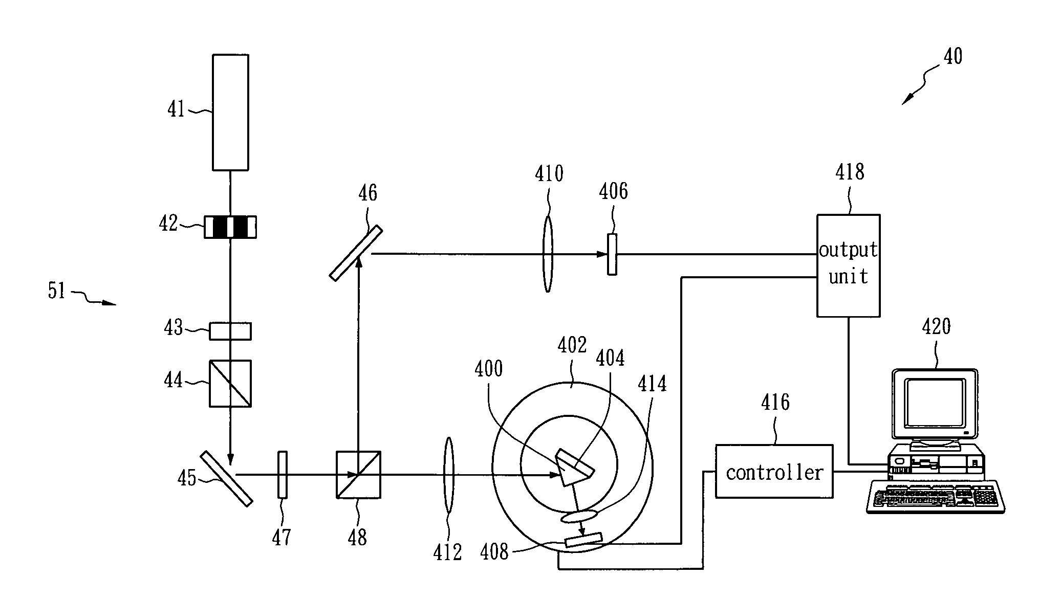
[0025]The lighting assembly provides an incident light beam containing TM wave. The light source of the incident light beam can be a laser light, a tungsten filament lamp, a mercury lamp, a light emitting diode (LED), synchronic radiating light, etc. The wavelength can be in the frequency band of infrared light, visible light, or ultraviolet light. And the TM wave can be generated in a manner of modulating by the use of an optical lens group or a polarizer. In order to reduce the noise of the incident light beam or adjust the percentage of the TM wave, optical components such as lenses, filters, and polarizers can be further disposed in the incident light path, which are regarded as a part of the lighting assembly.
[0034]The present invention can measure gaps with the widths of less than 100 nm or even 10 nm, and can be used for many applications. For example, it can be applied for a servo control system of the pick-up head for near-field optical discs, and can sense and control the distance between the pick-up head and the optical disk at near-field distances so as to assure the correctness and reliability of reading and writing. The present invention can be applied in a sub-nanometer photolithography system to sense the proximity distance between a mask and a silicon wafer, so as to improve the reliability of the system. Also, the present invention can be applied in sensing and controlling the gap of liquid crystal layers for new-generation LCDs, in surface curve plotters, or the like. With the development of various nanometer techniques, various micro-products have been developed. The present invention is applicable to the sensing units for sensing gap size and displacement shift or for precise distance control of the products and techniques, so it will have extensive applications in the future.

Problems solved by technology

However, there has been no breakthrough in the development of the method for measuring gap width of nanometer scale.
Therefore, the measuring method using normal visible light is not applicable for gap widths less than 300 nm, 100 nm, or 10 nm.
Therefore, the operation is inconvenient, and the stability is reduced due to the complicated structure.
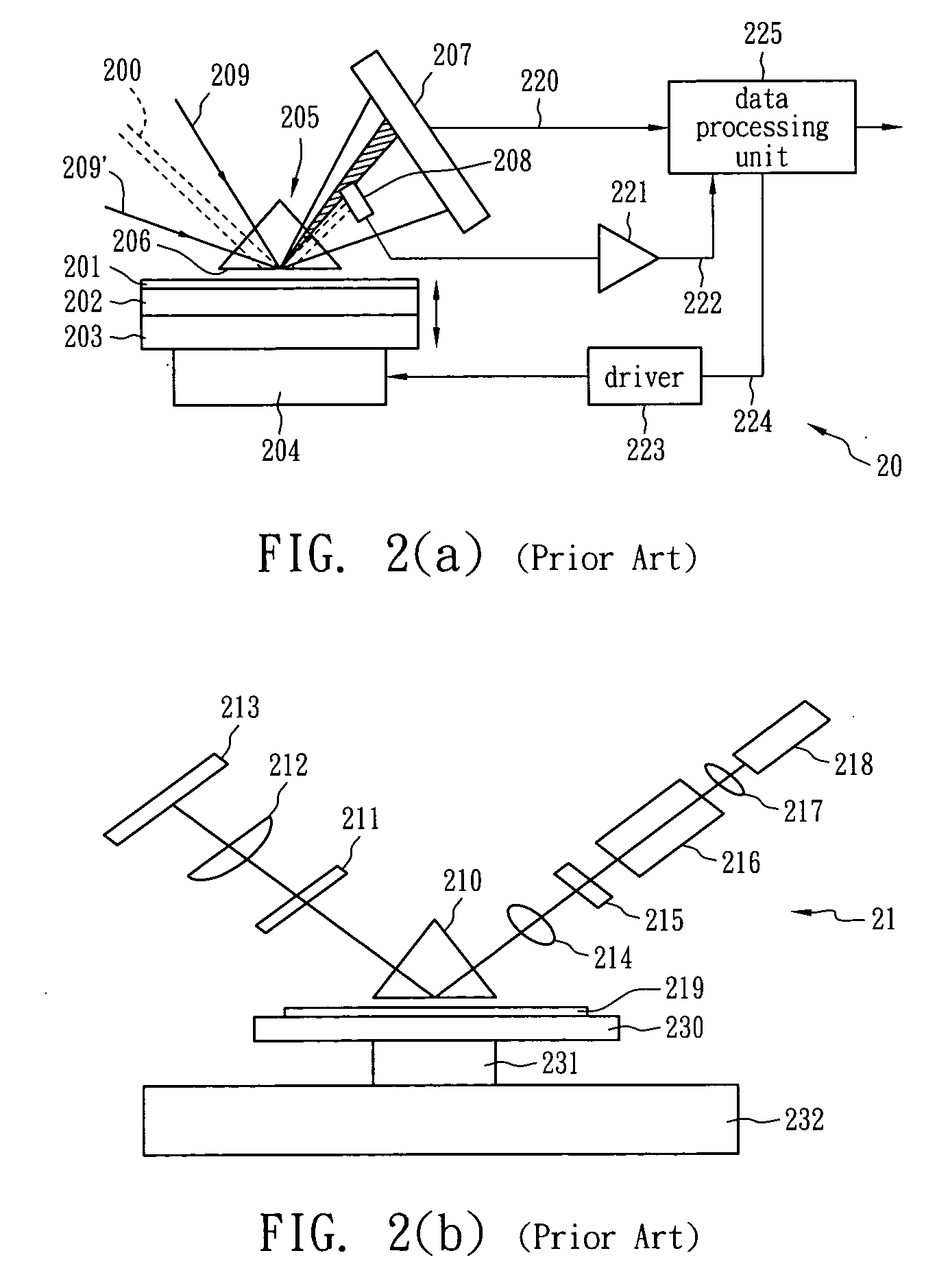
However, the Japanese patent is limited to the application of SPR of Otto configuration, and does not illustrate the relation between the corresponding changes of the resonance angle and the gap.
Also, the patent is only for controlling the distance between two subjects near the position of the resonance angle, so it is not applicable to measure gap width or displacement shift of two subjects.

Method used


Image

  • Measuring apparatus and method using surface plasmon resonance
  • Measuring apparatus and method using surface plasmon resonance
  • Measuring apparatus and method using surface plasmon resonance

Examples


Embodiment Construction

[0044]The corresponding relations of the reflective coefficients and various multi-layer interfaces can be calculated according to the optical Fresnel reflection theorem. The equation of the change of the reflectivity is expressed by:

R=r01232=r01+r123exp(j2kz1d1)1+r01r123exp(j2kz1d1)2(4)r123=r12+r23exp(j2kz2d2)1+r12r23exp(j2kz2d2)(5)rnm=(ɛmkzn-ɛnkzm) / (ɛmkzn+ɛnkzm)(6)kzm=kx2-ɛmkinc2(7)

[0045]where the subscript 0 represents the prism layer; 1 represents a metal layer; 2 represents the gap layer; 3 represents the relative subject to be measured, R is the reflectivity, r0123 is the reflective coefficient of the combination of the four layers, r123 is the reflective coefficient of the combination of the three layers, rnm is the reflective coefficient of any two neighboring layers n, m, εm is the dielectric coefficient of the m layer, dm is the thickness of the m layer, kzm is the z component of the wave vector of the m layer, kinc is the wave vector of the incident light, and kx is the x...


PUM


Abstract

An apparatus and a method for measuring gap width, displacement shift or relative position between two subjects using surface plasmon resonance (SPR) are disclosed. First, a TM mode light beam is provided, so as to generate SPR on a surface of one of the two subjects. Then, the signal of the reflective light or penetrative light on the surface is measured. Because SPR is sensitive to the changes of the gap, displacement shift or relative position when the width of the gap is equal to or smaller than twice the penetration length of the surface plasmon wave, the gap, displacement shift and relative position can be acquired by sensing changes of the signal. Accordingly, the width of the gap, displacement shift, relative position and surface roughness smaller than twice the penetration length or even less than 10 nm can be measured.

Description

RELATED U.S. APPLICATIONS[0001]Not applicable.STATEMENT REGARDING FEDERALLY SPONSORED RESEARCH OR DEVELOPMENT[0002]Not applicable.REFERENCE TO MICROFICHE APPENDIX[0003]Not applicable.FIELD OF THE INVENTION[0004]The present invention relates to an apparatus and a method for measuring small gap width, displacement shift, or relative position by means of surface plasmon resonance (SPR). More particularly, the present invention relates to an apparatus and a method for measuring nanometer-scale gap width, displacement shift, or relative position by SPR.BACKGROUND OF THE INVENTION[0005]For a long time, optical measuring methods in the science field mainly use optical interference measuring techniques. By analyzing some changes of interference fringes, the displacement shift of the relative subject can be calculated, and with more precise measuring apparatus, smaller changes of displacement shift can be detected. However, there has been no breakthrough in the development of the method for ...

Claims


Application Information

Patent Timeline
IPC IPC(8): G01N21/55
CPCG01N21/553G01B11/14
Inventor WU, PAO TUNGWU, CHIEN MING
Owner NATIONAL TSING HUA UNIVERSITY
Learn More